Introduction & General Principles of Extraction
Why metals occur as compounds, the three branches of extractive metallurgy, and the universal sequence of steps used to win a metal from its ore.
Contents
1 Occurrence of Metals in Nature
Metals occur in nature either in free (native) form or in combined form. Noble metals — gold (Au), silver (Ag), mercury (Hg), platinum (Pt) — show little affinity for oxygen, sulphur or moisture and may exist in the elemental state. Most metals are chemically active and combine with oxygen, sulphur, carbon dioxide, or halogens to form oxides, sulphides, carbonates, halides, and silicates.
The most abundant active substances in nature are O₂ and CO₂ (atmosphere) and S and Si (earth's crust). Consequently, the most important ore types are: (i) oxides, (ii) sulphides, (iii) carbonates, (iv) halides, and (v) silicates.
Driving force for extraction: The chemical potential difference between the metallic compound and the desired elemental metal. Every extraction process creates conditions under which the metal transfers from a high to a low chemical-potential state.
2 Minerals, Ores & Gangue
A mineral is any naturally occurring material in which a metal or its compound is present. An ore is a mineral from which the metal can be extracted economically. The unwanted rocky or earthy impurities associated with the ore are called gangue (or matrix).
3 Branches of Extractive Metallurgy
- Pyrometallurgy: High-temperature processing — smelting, roasting, converting.
- Hydrometallurgy: Aqueous leaching, solvent extraction, precipitation at near-ambient temperature.
- Electrometallurgy: Electrolytic decomposition of fused salts (Al, Mg) or electrolytic refining (Cu, Ni, Zn).
4 General Extraction Sequence
(i) Crushing and Pulverisation: Ore lumps are crushed in jaw crushers, then pulverised in stamp mills or ball mills to liberate the metal-bearing mineral grains from gangue.
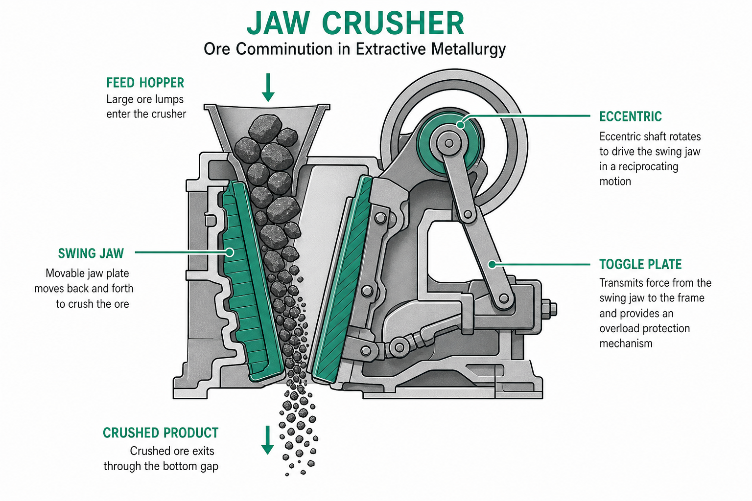
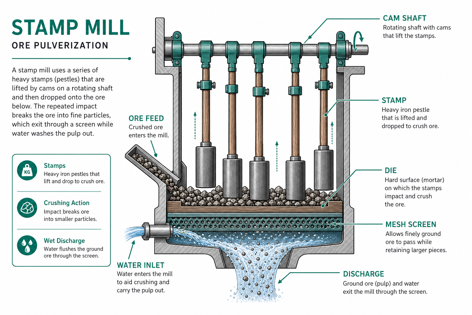
(ii) Concentration (Ore Dressing): Gangue is removed by gravity separation, magnetic separation, froth flotation, or chemical (leaching) methods to produce a concentrate.
(iii) Calcination or Roasting: The concentrate is heated — calcination in limited air drives off moisture and CO₂; roasting in excess air converts sulphides to oxides and expels SO₂.
(iv) Reduction: The oxide is reduced to metal by carbon (smelting), aluminium (aluminothermy), hydrogen, or electrolysis. Flux is added to combine gangue into fusible slag.
(v) Purification and Refining: Crude metal is purified by liquation, poling, distillation, zone refining, fire refining, or electrolytic refining.
Flux types: Basic flux (CaO, MgO) removes acidic gangue (SiO₂). Acidic flux (SiO₂) removes basic impurities (FeO). The resulting slag (e.g. CaSiO₃) floats on the denser molten metal and protects it from reoxidation.
5 Indian Mineral Resources
India's mineral reserves are classified into three groups:
- Adequate to Abundant: Al, Be, Cr, Fe, Mn, Mg, Ti, Zr, Th, rare earths — capable of export surplus.
- Inadequate: Cu, Au, Graphite, Pb, V, Zn, Ni, Cd, U, Sn — insufficient for domestic demand.
- Poor / Unknown: Bi, B, Co, Hg, Mo, Nb, Ag, W — not commercially exploitable at present.
Key: India has one of the world's largest bauxite deposits (East Coast) and abundant Th, Zr, Be. It is deficient in Cu, Zn, Pb, Sn, Co, and Ni.
Key Takeaways — Lecture 1
- Metals occur as oxides, sulphides, carbonates, halides, or silicates; noble metals occur natively.
- An ore = economically workable mineral; gangue = accompanying waste rock.
- Three branches: pyrometallurgy (heat), hydrometallurgy (aqueous), electrometallurgy (current).
- Universal steps: comminution → concentration → calcination/roasting → reduction → refining.
- India is abundant in Al, Ti, Zr but deficient in Cu, Zn, Pb, Sn.
Ore Dressing & Concentration Methods
Gravity separation, magnetic separation, froth flotation, and chemical leaching — principles, equipment, and applications for each method.
Contents
1 Purpose of Concentration
Raw ore contains only a small percentage of the desired metal (e.g., Cu ores carry 0.5–2% Cu). Ore dressing (beneficiation) removes gangue and concentrates the valuable mineral, typically achieving 15–35% metal content in the concentrate before smelting.
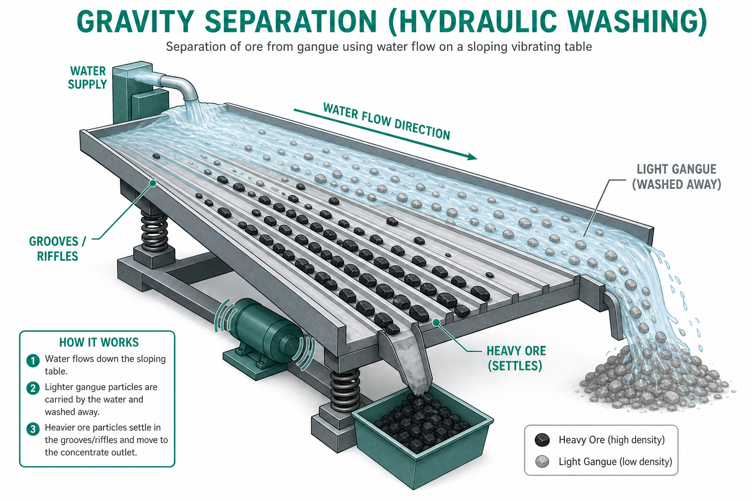
2 Gravity Separation (Hydraulic Washing)
Exploits the density difference between the heavy ore mineral and the lighter gangue. Powdered ore is agitated with water or washed by a strong current. Heavier ore particles settle in grooves while lighter gangue is washed away.
Applications: Heavier oxide ores — hematite (Fe₂O₃), tinstone (SnO₂), and gold (Au).
3 Magnetic Separation
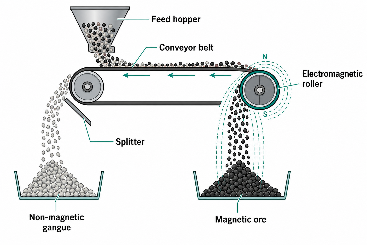
Used when either the ore or its gangue is magnetic. Powdered ore passes over a conveyor belt; one roll is fitted with an electromagnet. Magnetic particles are attracted and fall separately from non-magnetic material.
Example: Tinstone (SnO₂) is non-magnetic but contains magnetic impurities — iron tungstate (FeWO₄) and manganese tungstate (MnWO₄) — which are removed magnetically.
4 Froth Flotation
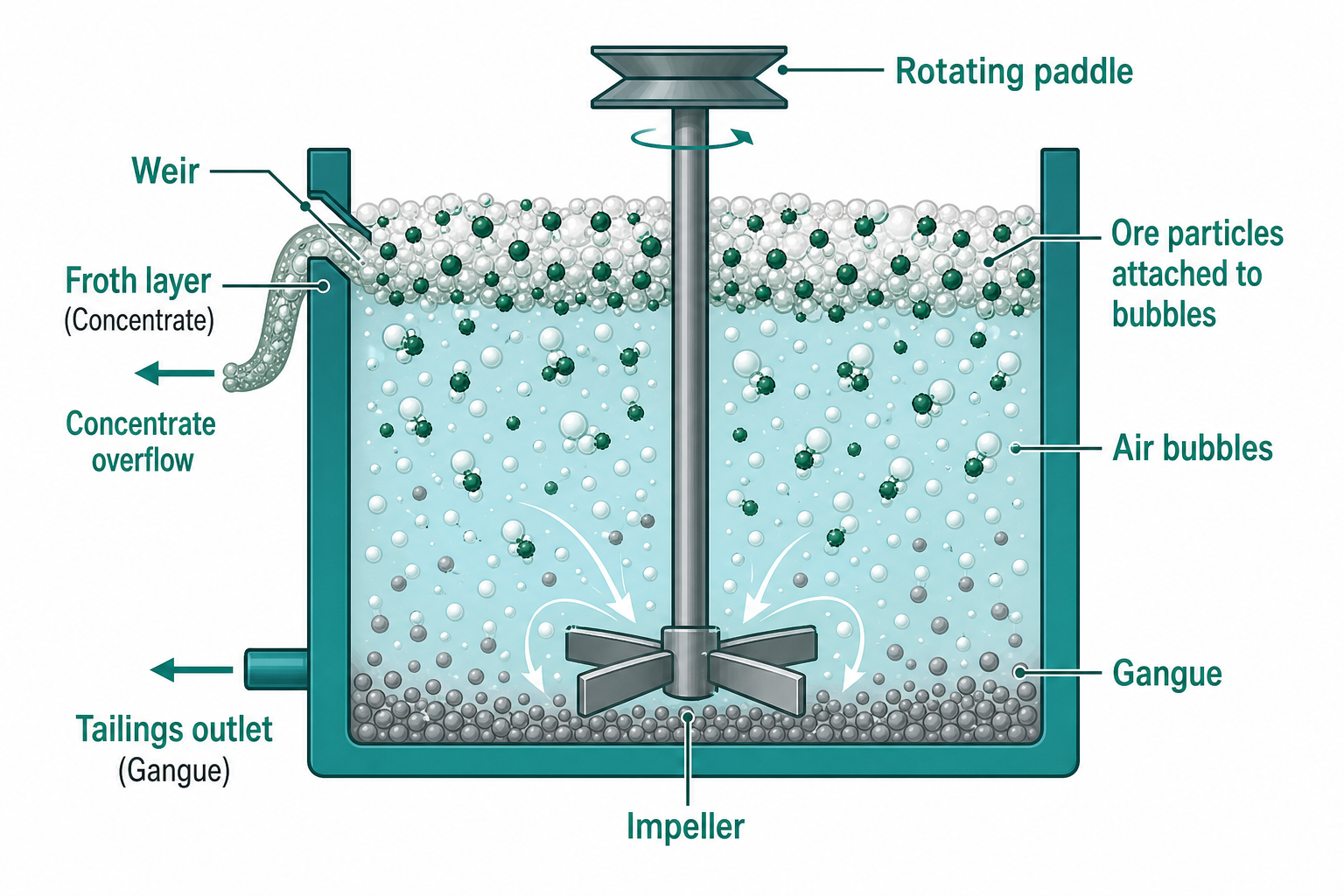
The most important concentration method for sulphide ores (galena PbS, sphalerite ZnS, chalcopyrite CuFeS₂). Exploits differential wettability of ore and gangue surfaces:
- Collectors (e.g., xanthates): Adsorb on mineral surfaces, rendering them hydrophobic so they attach to air bubbles.
- Frothers (e.g., pine oil, MIBC): Stabilise the froth layer.
- Depressants / pH modifiers (e.g., CaO): Selectively depress unwanted minerals for differential flotation.
5 Chemical (Leaching) Method
The ore is dissolved in a selective chemical reagent, leaving insoluble impurities behind. Metal is then recovered by precipitation or electrolysis.
Example — Bayer process (Al): Bauxite digested with NaOH at 150–220 °C. Al₂O₃ dissolves as NaAlO₂; Fe₂O₃, TiO₂, SiO₂ remain as red mud. Al(OH)₃ precipitated from the cooled liquor and calcined to Al₂O₃.
Cyanidation (Au, Ag): Argentite (Ag₂S) dissolves in dilute NaCN to form [Ag(CN)₂]⁻. Silver is recovered by adding zinc: Zn + 2[Ag(CN)₂]⁻ → [Zn(CN)₄]²⁻ + 2Ag.
Key Takeaways — Lecture 2
- Gravity separation: density difference; for heavy oxide ores (SnO₂, Fe₂O₃).
- Magnetic separation: removes magnetic gangue (FeWO₄) from non-magnetic ore (SnO₂).
- Froth flotation: differential wettability; standard for sulphide ores; uses collectors, frothers, depressants.
- Chemical leaching: selective dissolution; Bayer process for Al; cyanidation for Au/Ag.
Roasting, Smelting & Refining Techniques
Converting concentrated ore to metal oxide by calcination or roasting, reducing it to crude metal by smelting, and purifying by fire refining and electrolytic refining.
Contents
1 Calcination vs Roasting
Calcination: Heating in limited air below the melting point. Drives off moisture, water of hydration, and CO₂. Example: Al(OH)₃ → Al₂O₃ + H₂O; CaCO₃ → CaO + CO₂.
Roasting: Heating in excess air below fusion. Converts sulphide to oxide, expels SO₂, dries ore, removes volatile impurities. SO₂ produced is used to manufacture H₂SO₄.
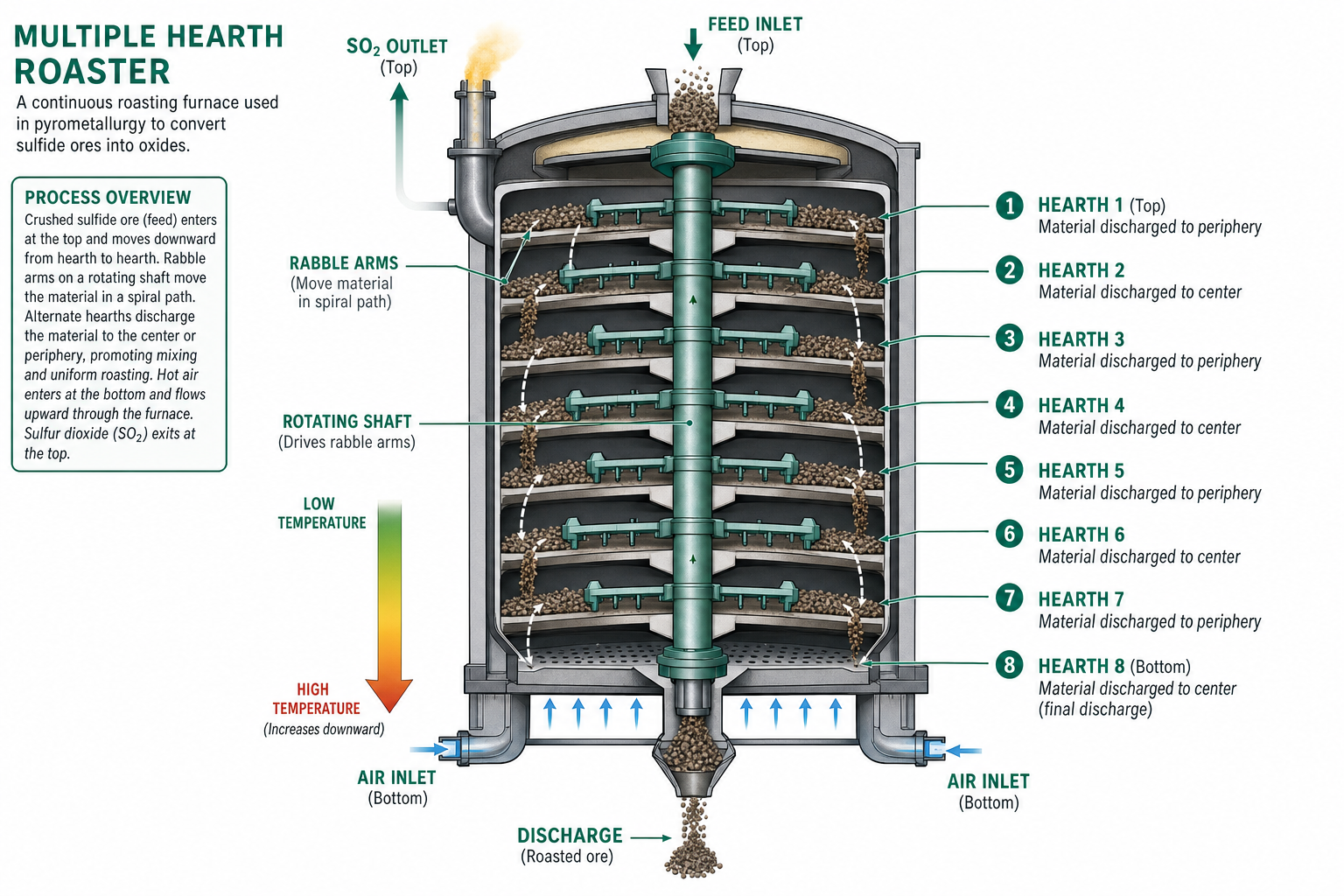
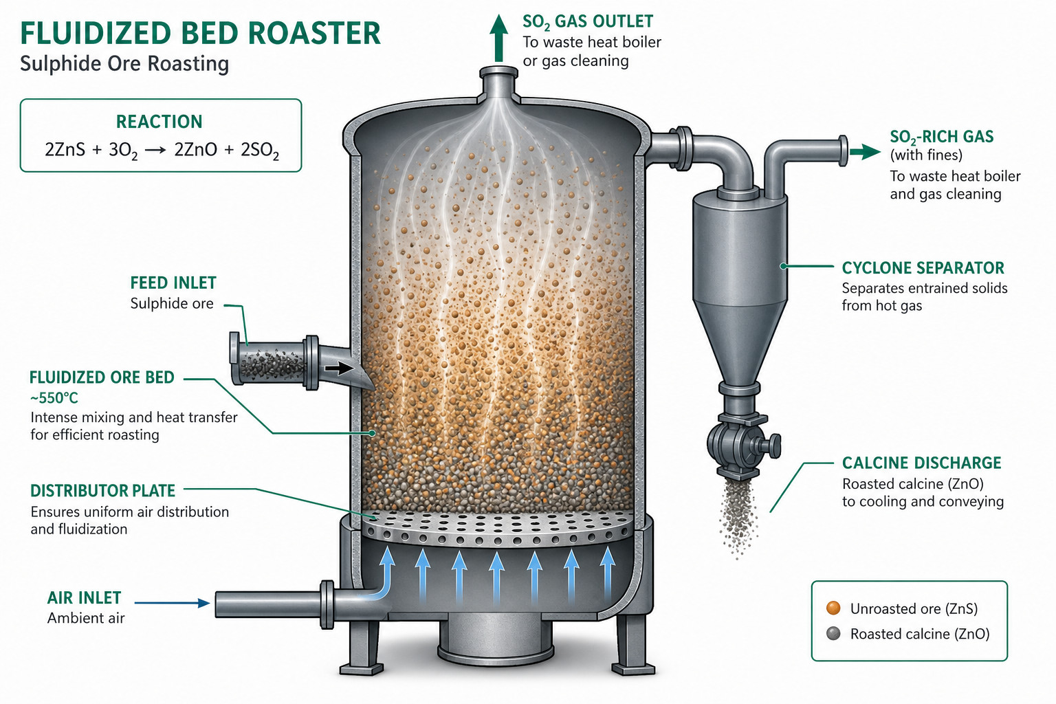
Key roasting reactions: 2ZnS + 3O₂ → 2ZnO + 2SO₂ | 2CuFeS₂ + 4O₂ → Cu₂S + 2FeO + 3SO₂. Equipment: multiple-hearth roaster (conventional) or fluidised-bed roaster (modern).
2 Smelting & Flux Chemistry
Smelting reduces the oxide (or calcine) to metal using carbon or other reducing agents, with flux to remove gangue as slag. Two immiscible layers: denser metallic/matte layer below; lighter slag above.
- Basic flux (CaO): removes acidic gangue → CaO + SiO₂ → CaSiO₃ (slag).
- Acidic flux (SiO₂): removes basic impurities → SiO₂ + 2FeO → Fe₂SiO₄ (slag).
3 Reduction Methods
- Carbon reduction: ZnO + C → Zn + CO; SnO₂ + 2C → Sn + 2CO.
- Metallothermic (aluminothermy): Cr₂O₃ + 2Al → 2Cr + Al₂O₃ — highly exothermic; for Cr, Mn.
- Self-reduction: Cu₂S + 2Cu₂O → 6Cu + SO₂ — applied to Cu, Pb, Hg sulphide ores.
- Electrolytic reduction: Active metals (Al, Mg, Na) — fused-salt electrolysis.
4 Purification & Refining
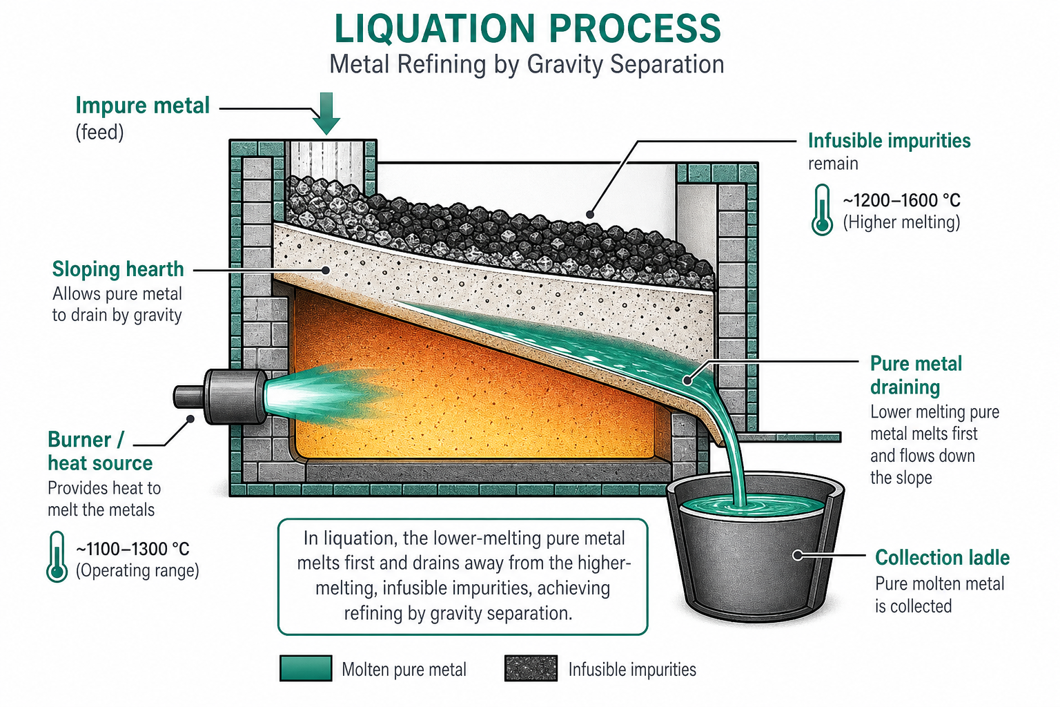
Liquation: Crude metal heated just above M.P. on sloping hearth; pure metal drains, leaving infusible impurities. Used for Sn, Pb.
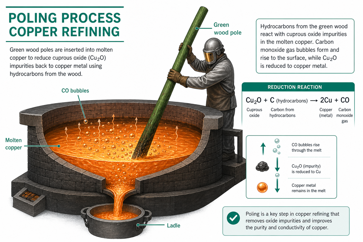
Poling: Green wood is stirred through molten Cu or Sn; hydrocarbons reduce Cu₂O impurity back to Cu.
Distillation: Volatile metals (Zn, Hg) are purified by distillation; non-volatile impurities remain.
Electrolytic refining: Impure metal cast as anode; pure metal deposited on cathode in appropriate metal-salt electrolyte. Noble impurities collect as anode slime (Au, Ag, Pt). Purity: up to 99.99%.
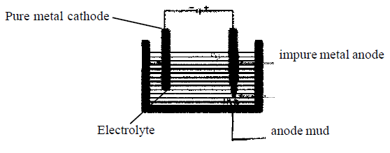
Anode mud in Cu electrolytic refining contains Au, Ag, Pt, Se, Te — recovered as valuable by-products. This significantly improves the economics of copper refining.
Key Takeaways — Lecture 3
- Calcination (limited air) → removes H₂O, CO₂; Roasting (excess air) → converts sulphide to oxide, produces SO₂.
- Smelting uses flux to slag gangue: basic flux (CaO) for acidic gangue; acidic flux (SiO₂) for basic gangue.
- Reduction: C-reduction (Zn, Sn); aluminothermy (Cr, Mn); electrolysis (Al, Mg, Na).
- Electrolytic refining gives highest purity; anode mud contains Au, Ag — major revenue stream.
Extraction of Copper — Conventional Route
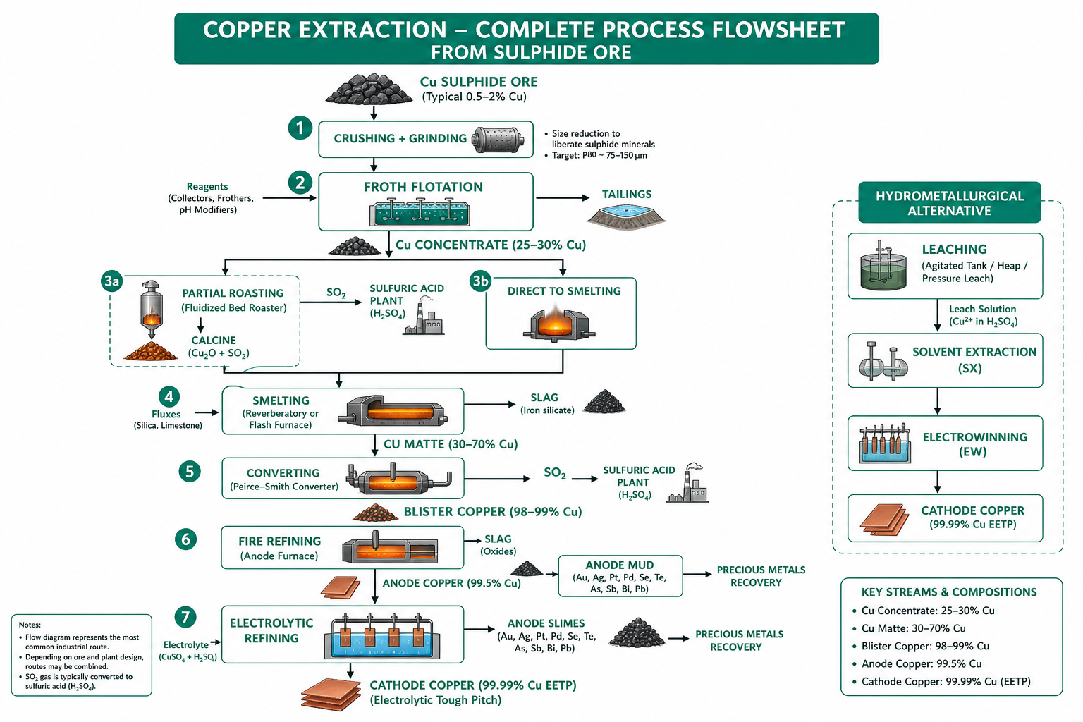
From chalcopyrite concentrate to blister copper: concentration → roasting → smelting → converting → fire refining → electrolytic refining.
1 Properties & Minerals of Copper
At. No. 29 | At. Wt. 63.54 | Density 8.94 g/cm³ | M.P. 1083 °C | B.P. 2595 °C.
Key minerals: Chalcopyrite (CuFeS₂) — chief ore; Chalcosite (Cu₂S); Bornite (Cu₅FeS₄); Cuprite (Cu₂O); Malachite (CuCO₃·Cu(OH)₂); Azurite (2CuCO₃·Cu(OH)₂). Indian deposits: Singhbhum belt (Bihar), Khetri (Rajasthan).
2 Concentration & Roasting
A natural Cu sulphide ore contains only 0.5–2% Cu. After crushing and grinding (~40 μm), froth flotation using CaO (pH control) and xanthate (collector) produces concentrate with 15–35% Cu, 15–35% Fe, 25–35% S, 3–15% gangue.
Roasting (if high FeS₂ content, <25% Cu): partial oxidation at ~550 °C in multiple-hearth or fluidised-bed roaster. SO₂ → H₂SO₄ plant.
3 Smelting to Matte
Calcine is smelted with siliceous flux at ~1250 °C. Two immiscible layers form: slag (SG 2.8–3.8, iron silicate, floats) and matte (SG 5.0–5.5, Cu₂S–FeS mixture, 35–45% Cu). Key exchange reaction: FeS + Cu₂O → Cu₂S + FeO (O₂ has greater affinity for Fe than Cu per Ellingham diagram).
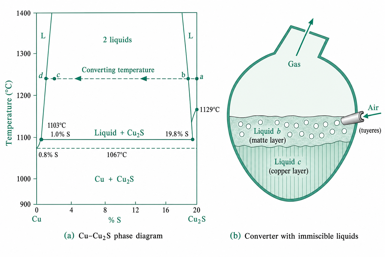
4 Converting
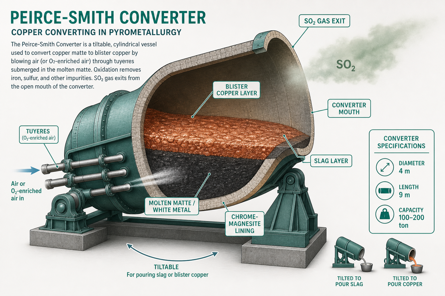
A side-blown Peirce-Smith converter (4 m dia., 9 m long, 100–200 t capacity) receives molten matte and blows O₂-enriched air through 40 tuyeres (5 cm dia.). Two stages:
- Slagging stage: FeS oxidised; FeO + SiO₂ → converter slag (2–9% Cu); skimmed off.
- Blister-formation stage: Cu₂S (white metal) oxidised → blister Cu (~98.5–99.5%) + SO₂. Cu₂S + O₂ → 2Cu + SO₂.
5 Refining
Fire refining (reverberatory furnace, 400 t): oxidise S, Fe, Se, Zn → skim. Poling with green wood reduces Cu₂O. Purity: 99.97%.
Electrolytic refining: Crude Cu anode in CuSO₄/H₂SO₄ electrolyte at 50–60 °C. Cu deposits at cathode (99.99%); Fe, Co, Ni go into solution; Au, Ag, Pt, Se, Te → anode mud.
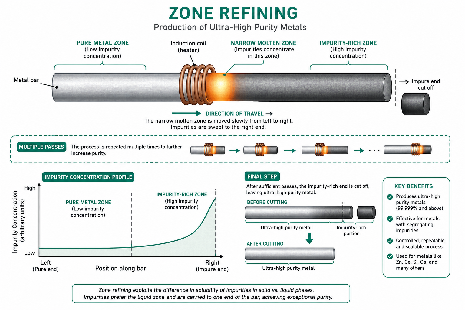
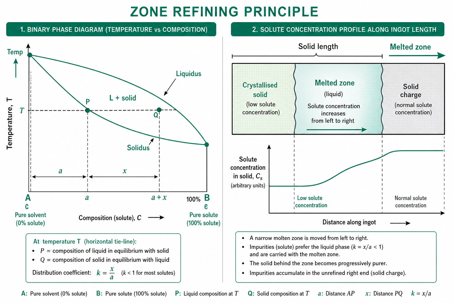
Zone Refining (for ultra-high purity): A narrow molten zone traverses a bar slowly; impurities concentrate in the melt and migrate to one end.
Key Takeaways — Lecture 4
- Cu ore (0.5–2%) → flotation → concentrate (15–35% Cu) → smelting → matte (35–45% Cu).
- Smelting exploits greater O₂ affinity for Fe vs Cu; FeS → FeO → slag; Cu₂S retained in matte.
- Converting: Peirce-Smith converter, two stages — slagging + blister formation; product ~98.5–99.5% Cu.
- Electrolytic refining gives 99.99% Cu; anode mud Au/Ag recovery improves economics significantly.
Extraction of Copper — Modern Processes
Flash smelting (Outokumpu), and continuous smelting-converting processes: WORCRA, Noranda, and Mitsubishi — principles, efficiency, and economics.
1 Why Modern Processes?
Conventional reverberatory furnace smelting has low SO₂ concentration in off-gas, high fuel consumption, and batch operation. Modern processes use autogeneous (self-heating) reactions with O₂-enriched air, generating rich SO₂ gas and enabling continuous operation.
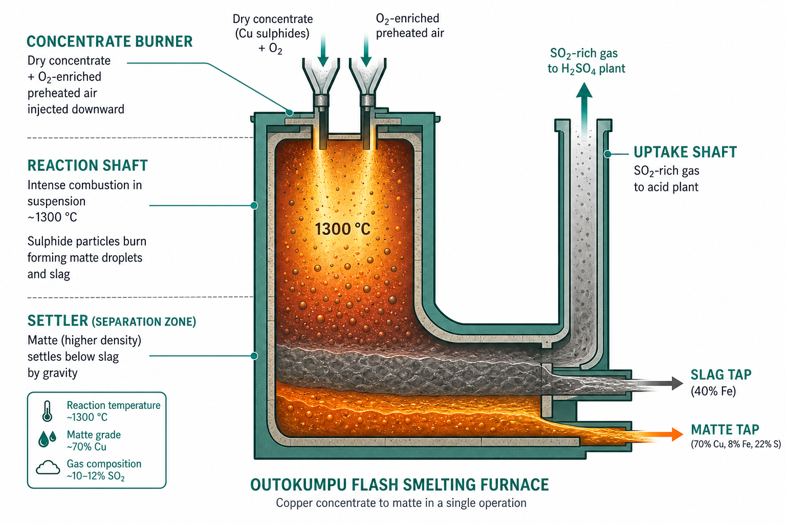
2 Flash Smelting (Outokumpu)
Dry concentrate is blown with preheated O₂-enriched air into a reaction shaft. Sulphide particles combust in suspension at ~1300 °C, releasing SO₂ and producing high-Cu matte (70% Cu) in a single step.
- Autogeneous: exothermic sulphide oxidation provides all process heat.
- High SO₂ (20–70%): ideal for H₂SO₄ production.
- Products: Matte (70% Cu, 8% Fe, 22% S) + slag (40% Fe).
3 WORCRA Process
Combines smelting and converting in a single continuous reactor using counter-current movement of gas and concentrate. Features: directly produces blister Cu (not matte); no separate converter needed; continuous SO₂ extraction. Disadvantages: refractory lining not durable; high operating cost.
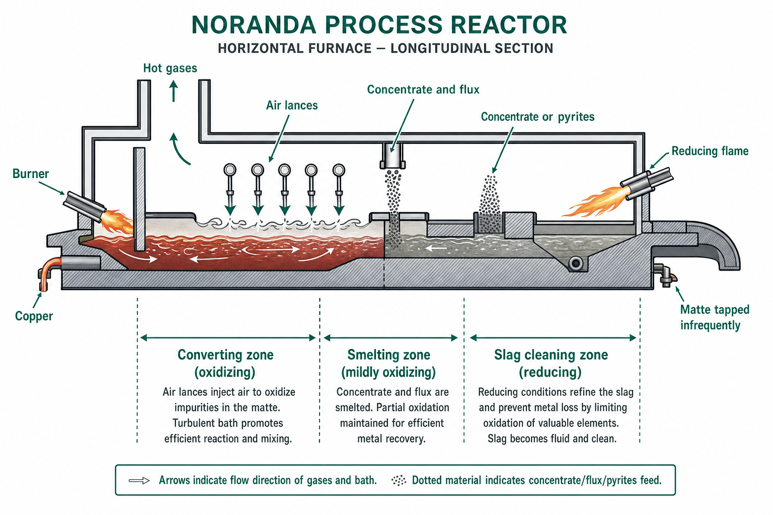
4 Noranda Process
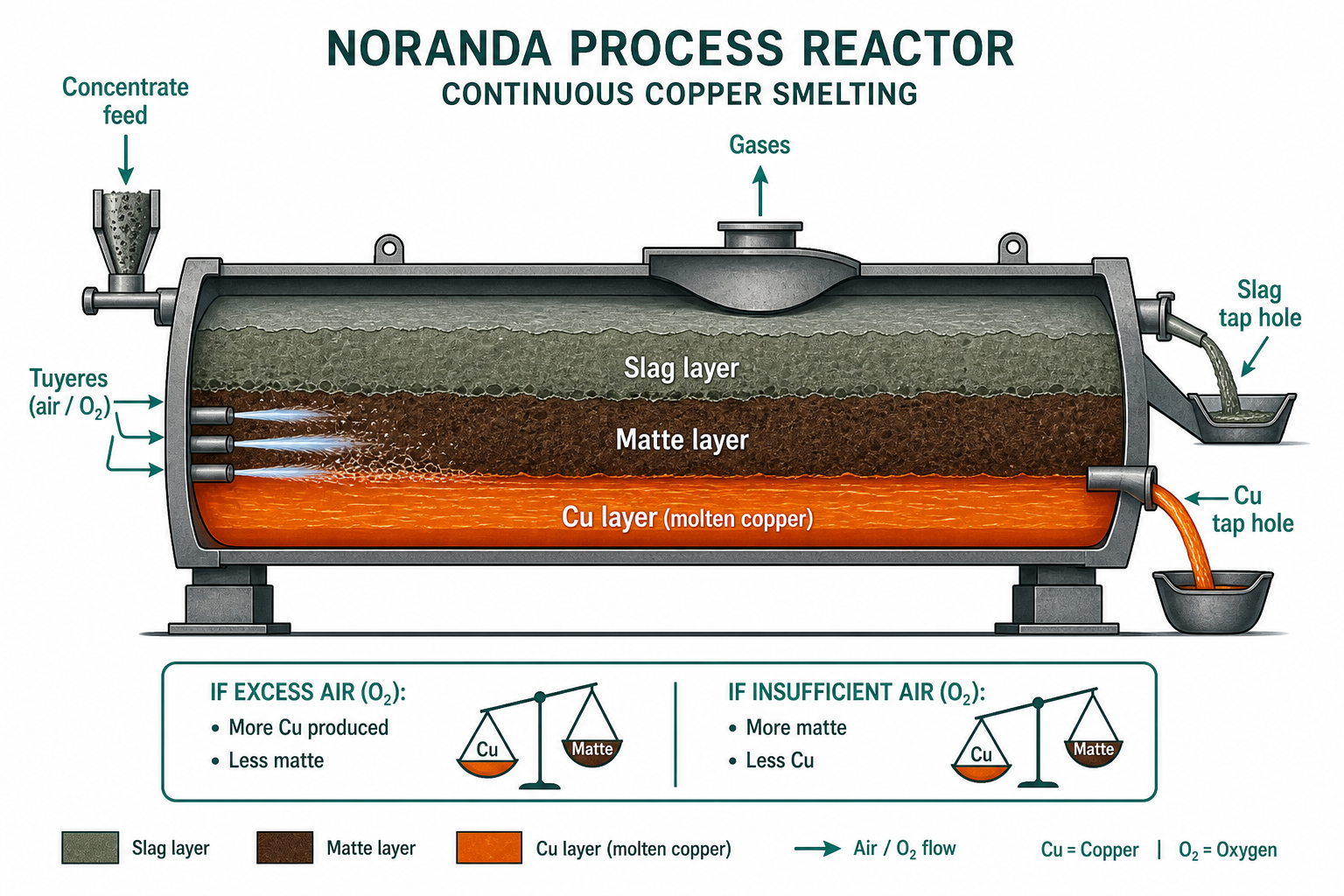
High-grade Cu matte or blister Cu forms directly from sulphide concentrate in a horizontal reactor. Air blown through tuyeres oxidises matte. Three layers: Cu (bottom), matte (middle), slag (top).
5 Mitsubishi Process
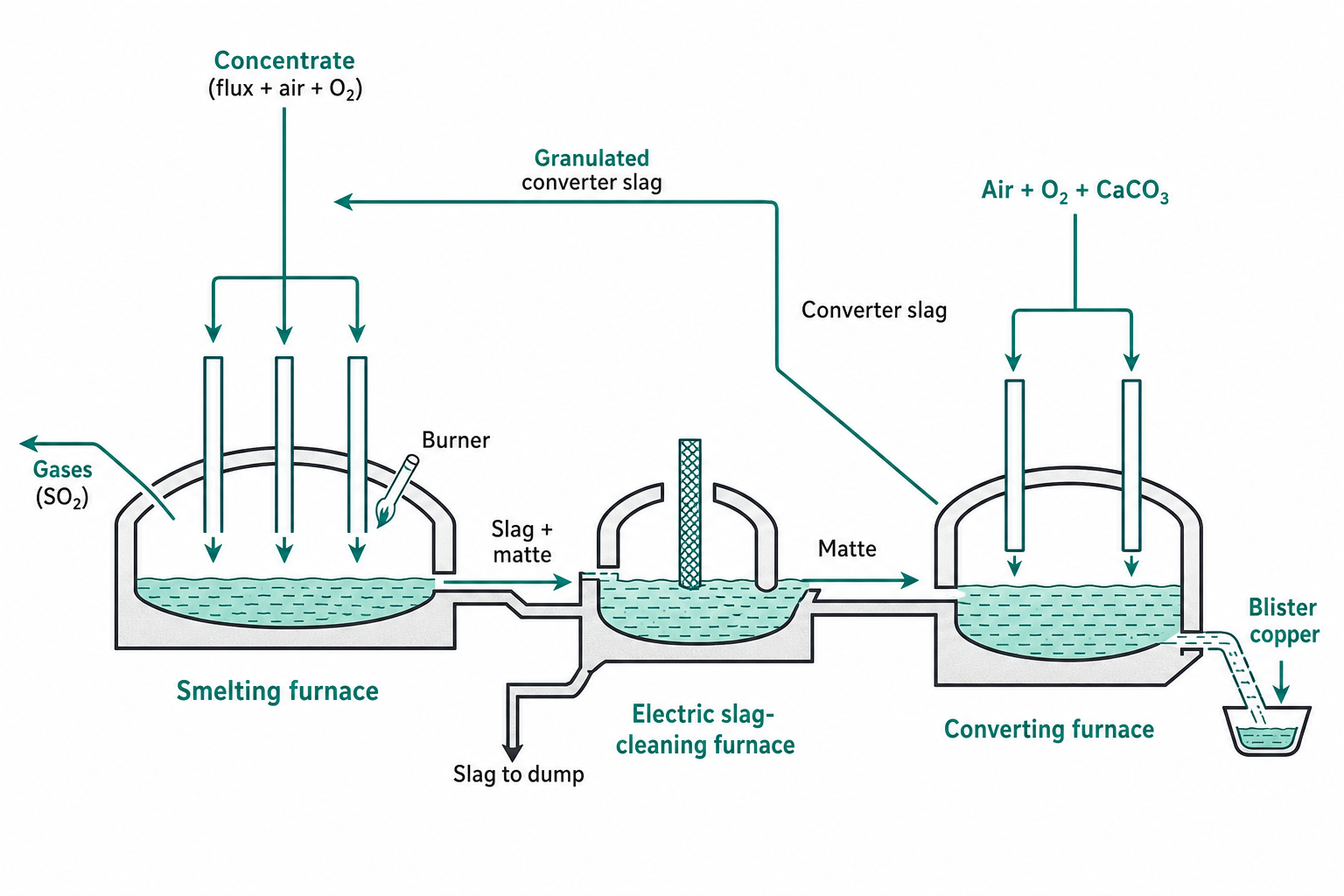
Three furnaces in cascade connected by gravity launders — smelting furnace → slag-cleaning furnace → converting furnace. Each stage operates continuously:
- Smelting furnace: wet concentrate + flux + O₂ → matte (60–65% Cu) + slag.
- Slag-cleaning furnace: slag gravity-separated; matte passes to converter.
- Converting furnace: matte + O₂-enriched air + limestone → blister Cu + lime-ferrite slag.
Mitsubishi process advantages: fully continuous; gravity transport eliminates ladles; each furnace optimised for its specific reaction; SO₂-rich off-gas directly captured. Used at Naoshima (Japan).
Key Takeaways — Lecture 5
- Flash smelting: autogeneous, O₂-enriched; matte 70% Cu; rich SO₂ for acid plant; ~50% world Cu production.
- WORCRA: single vessel, smelting + converting, counter-current; directly produces blister Cu.
- Noranda: horizontal reactor, three layers; high Cu-in-slag requires slag cleaning step.
- Mitsubishi: three-furnace gravity cascade, fully continuous; best SO₂ capture and environmental compliance.
Extraction of Zinc
Five routes to zinc metal — horizontal retort, vertical retort, electrothermic, electrolytic, and Imperial Smelting — and the slag fuming process for Zn recovery from slag.
Contents
1 Properties & Minerals of Zinc
At. No. 30 | At. Wt. 65.38 | Density 7.13 g/cm³ | M.P. 419.5 °C | B.P. 910 °C.
Minerals: Sphalerite (ZnS, zinc blende) — chief ore; Zincite (ZnO); Smithsonite (ZnCO₃); Willemite (Zn₂SiO₄); Franklinite. Indian deposits: Zawar mines (Rajasthan), HZL.
2 Roasting & Sintering
ZnS cannot be smelted directly (does not melt even at 1500 °C). Concentrate (~55% Zn) is roasted to ZnO in a fluidised-bed roaster (autogeneous, high SO₂). ZnO is sintered for handling. Hearth roaster used for initial volatilisation of Pb impurities.
Key roasting reaction: 2ZnS + 3O₂ → 2ZnO + 2SO₂. The fluidised-bed roaster is preferred as it is autogeneous, generates rich SO₂ (suitable for H₂SO₄), and gives high throughput with good temperature control.
3 Retort Processes & Electrolytic
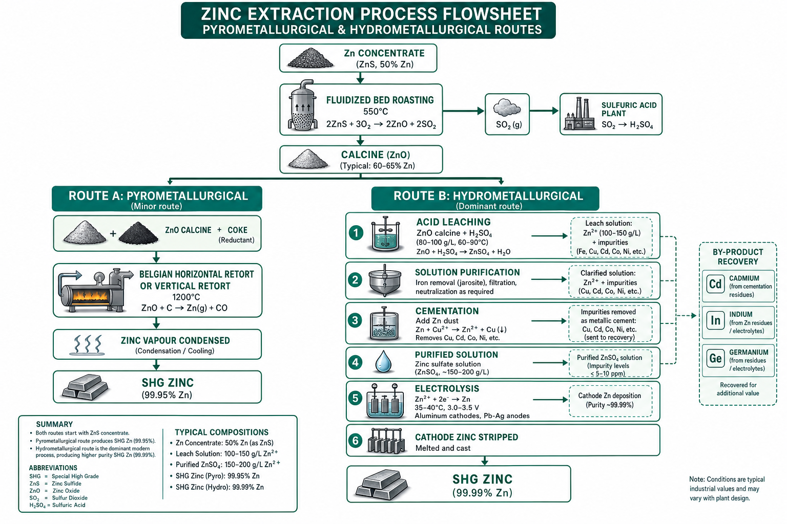
- Horizontal retort: 2 m long, 25 cm dia. clay retort; ZnO + coke breeze at 1400 °C; Zn volatilises and condenses. Low capacity, batch.
- Vertical retort: 10 m tall, 70 cm dia., SiC walls (5× conductivity of horizontal); 7–10 t Zn/day.
- Electrothermic: 15 m vertical retort, 100 t Zn/day; graphite electrodes; off-gas contains 40–45% Zn vapour.
- Electrolytic process: Highest purity (~99.95%); ZnO dissolved in H₂SO₄; electrolysed with Al cathodes and Pb-Ag anodes. Si rectifiers reduce power consumption.
All retort-derived Zn (spelter) further refined by fractional distillation: Zn B.P. 907 °C, Cd 780 °C, Pb 1620 °C — wide separation facilitates purification.
4 Imperial Smelting Process (ISP)
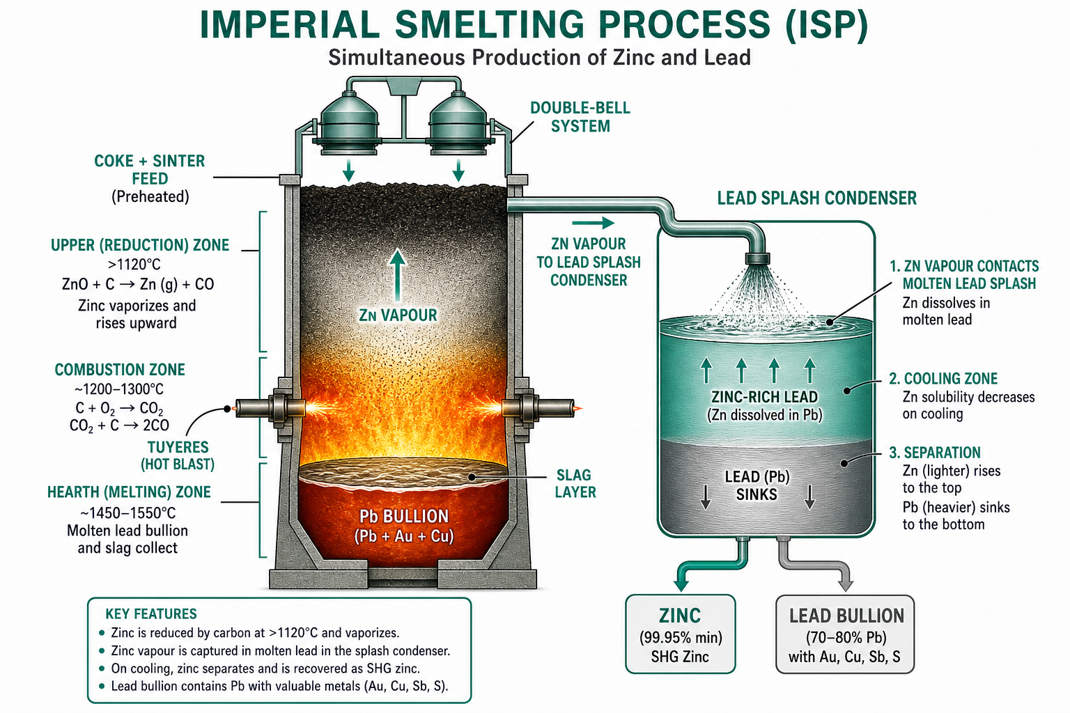
The ISP blast furnace handles mixed Zn–Pb concentrates simultaneously — unique process that recovers both metals. Preheated coke charged from top; sinter via double-bell system. ZnO + C → Zn vapour (at >1120 °C); condensed in molten-lead splash condenser. Pb bullion (70–80% Pb + Au, Cu, Sb) collected at hearth.
5 Slag Fuming & Uses
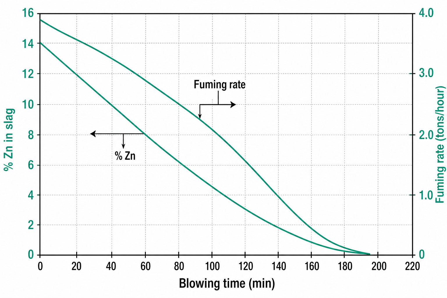
Slag fuming process (COMINCO): Slag from the lead blast furnace (15–18% Zn) is treated with pulverised coal + air through tuyeres. Zn is volatilised and oxidised to ZnO fume, collected in a bag house. Fume dispatched to electrolytic Zn plant.
Uses of Zn: Galvanising steel (cathodic protection); die-casting alloys; Cu-Zn brasses (30–37% Zn); ZnO pigments; Zn spraying for corrosion protection.
Key Takeaways — Lecture 6
- ZnS cannot be smelted directly — must be roasted to ZnO first.
- Retort processes: horizontal → vertical → electrothermic, increasing capacity and efficiency.
- ISP: blast furnace reduces ZnO; lead condenser captures Zn vapour; co-produces Zn + Pb bullion (with Au, Cu).
- Electrolytic process: highest purity (99.95%); dominates modern Zn production.
- Slag fuming recovers Zn from Pb blast furnace slag; sends ZnO fume to electrolytic plant.
Extraction of Lead
From galena to high-purity lead: sintering, blast furnace reduction, and the cascade of refining steps — liquation, drossing, softening, Parkes desilverising, and dezincing.
Contents
1 Properties & Minerals of Lead
At. No. 82 | At. Wt. 207.21 | Density 11.34 g/cm³ | M.P. 327.4 °C | B.P. 1737 °C.
Minerals: Galena (PbS) — chief ore; Cerussite (PbCO₃); Anglesite (PbSO₄). Indian: HZL (Tundoo, Bihar) and Visakhapatnam (15,000 t/yr).
2 Roasting, Sintering & Blast Furnace
Galena concentrate is roasted to oxides then sintered in a Dwight-Lloyd sintering machine (S reduced from 16–18% to 1–2%). Up-draught sintering preferred (higher capacity, better SO₂ recovery).
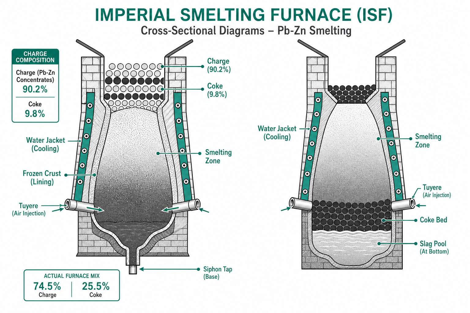
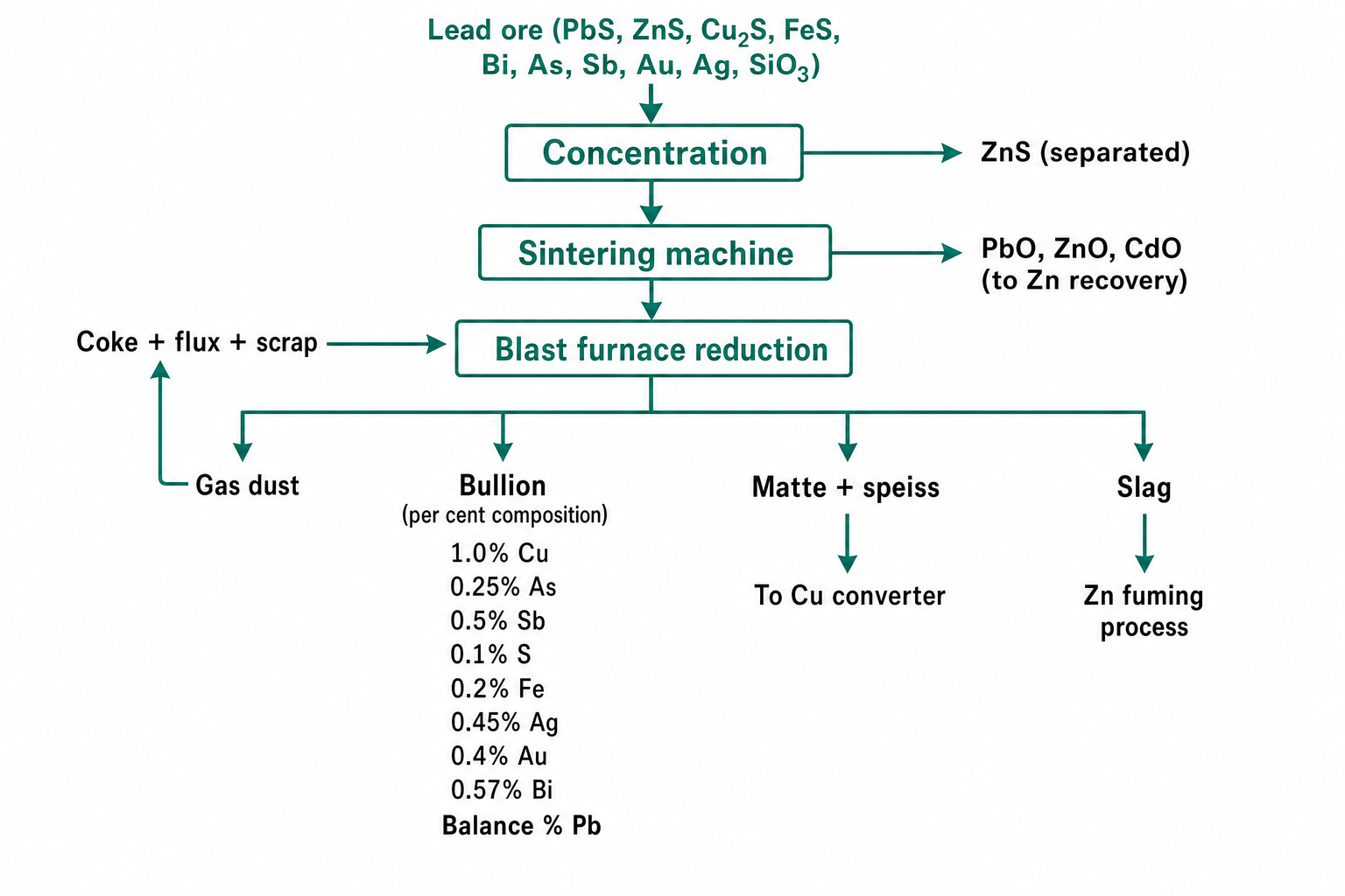
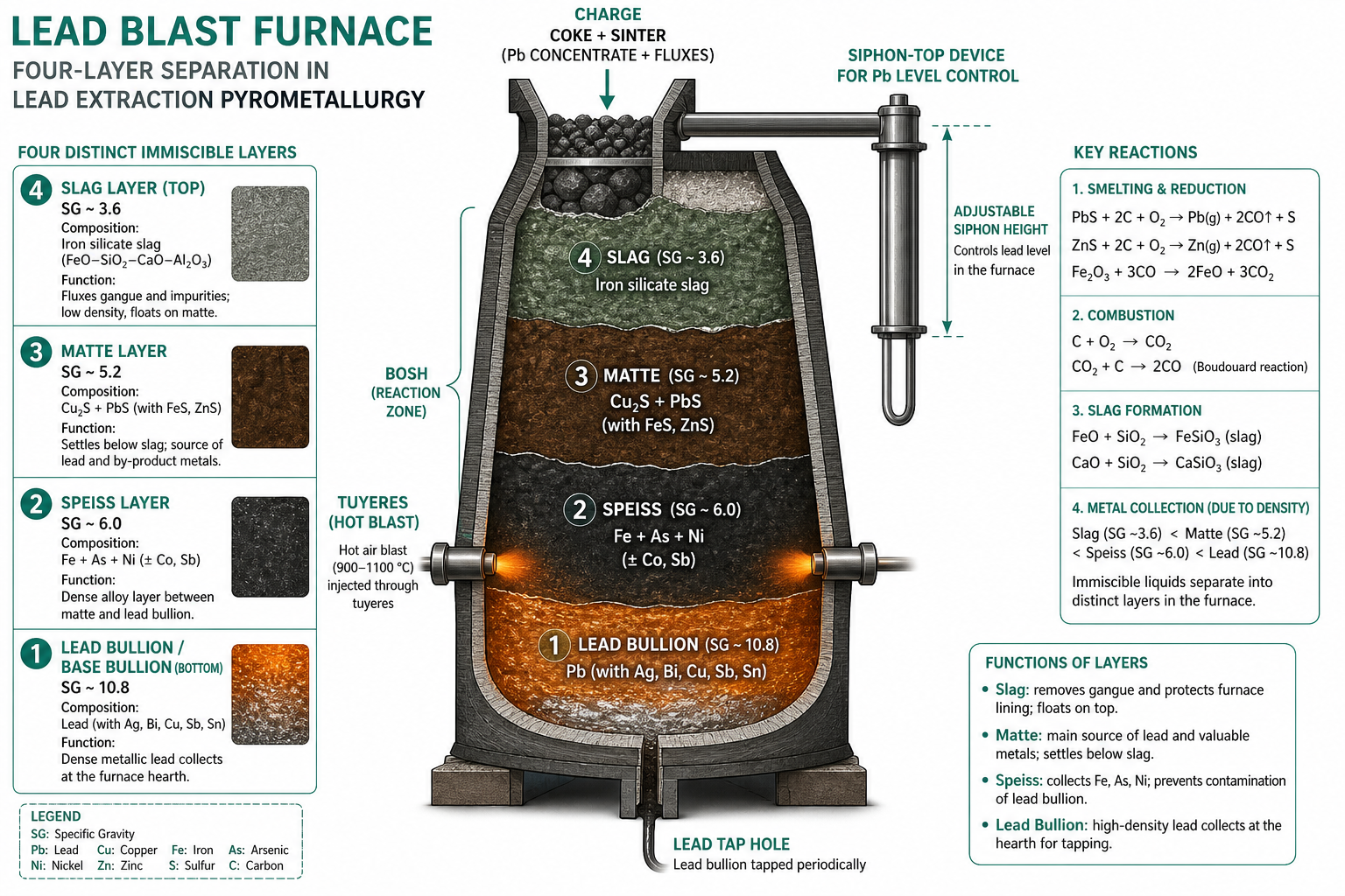
In the blast furnace, sinter is reduced with coke and siliceous flux. Four distinct layers form by specific gravity at the hearth:
- Slag (SG ~3.6): iron silicate — discarded.
- Matte (SG ~5.2): Cu₂S + PbS — returned for Cu recovery.
- Speiss (SG ~6): Fe-As-Ni alloy (when As + Fe → speiss); contains recoverable Cu.
- Lead bullion (SG ~10.8): crude Pb tapped continuously.
3 Refining of Lead Bullion
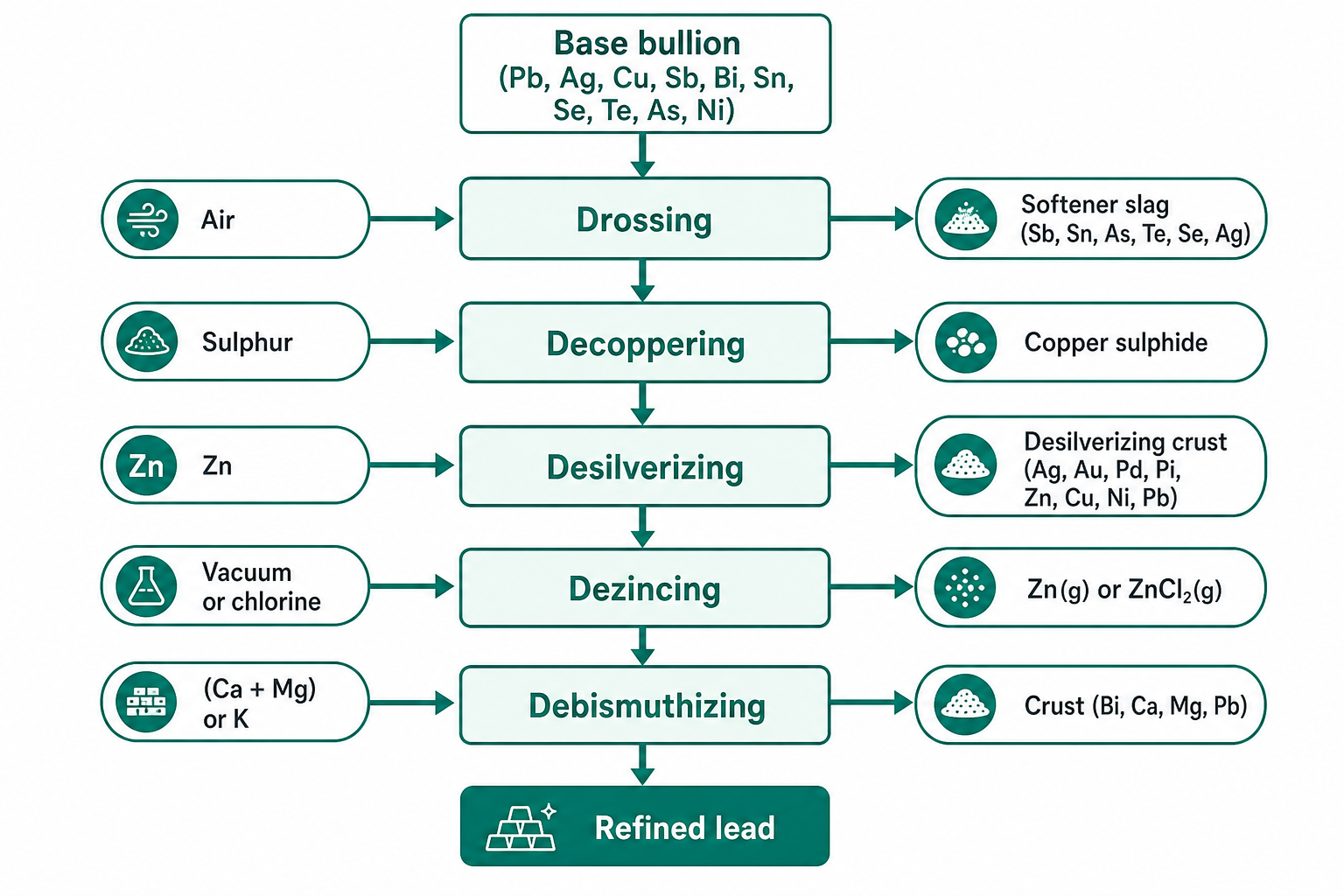
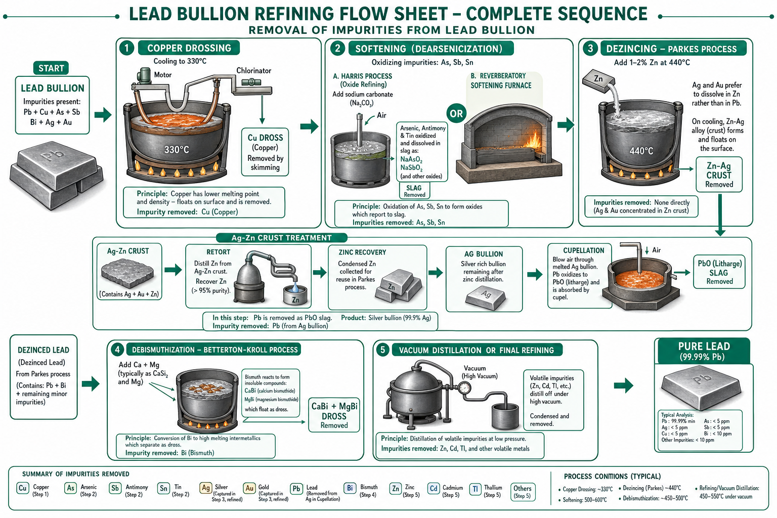
Lead bullion contains Sb, Sn, As, Bi, Cu, Ag, Au. Cascade refining:
- Liquation (drossing): Heated at 350 °C → Cu₂S dross skimmed; raised to 500–550 °C → Cu eliminated as Cu₂S.
- Softening: Sb, Sn, As oxidised and skimmed in a reverberatory furnace — gives soft, malleable Pb with improved corrosion resistance.
4 Parkes Desilverising & Dezincing
Parkes Process: Zn added to molten Pb; Zn has greater affinity for Ag and Au than Pb. Zn layer (higher M.P.) solidifies first, carrying Ag/Au. Cupellation recovers Ag: Zn-Pb-Ag alloy heated in reverberatory furnace with air blast → Pb and Zn oxidise to litharge/ZnO; pure Ag remains in the cupel.
Dezincing: Residual Zn removed by: (a) Cl₂ treatment — ZnCl₂ skimmed off; (b) Vacuum dezincing at 540 °C — Zn reduced from 0.6% to 0.002% in Pb.
Debismuthising: Ca and Mg added to form insoluble Ca-Mg-Bi intermetallic compound, skimmed off.
5 Electrolytic Refining
Pb bullion anode in H₂SiF₆ + PbSiF₆ electrolyte. Pure Pb deposits at cathode; Bi and precious metals → anode slime. Purity: 99.99%.
Uses of Pb: Lead-acid batteries; cable sheathing; Pb pigments (white lead 2PbCO₃·Pb(OH)₂, red lead Pb₃O₄); radiation shielding; Pb-Sb alloys for bearings.
Key Takeaways — Lecture 7
- Blast furnace produces four layers: slag / matte / speiss / lead bullion. Speiss = Fe-As phase.
- Refining cascade: drossing → softening → Parkes desilverising → dezincing → debismuthising.
- Parkes process: Zn preferentially picks up Ag/Au; cupellation then recovers Ag/Au from the Zn crust.
- Dezincing: Cl₂ treatment or vacuum distillation reduces Zn from 0.6% to 0.002% in Pb.
Extraction of Nickel
The INCO process for Ni extraction from Cu-Ni sulphide ore, Mond's carbonyl refining, and electrolytic refining of Ni to 99.95%.
Contents
1 Properties & Minerals of Nickel
At. No. 28 | At. Wt. 58.69 | Density 8.98 g/cm³ | M.P. 1452 °C | B.P. 2900 °C.
Minerals: Pentlandite [(NiFe)₉S₈] — chief ore; Violarite [Ni₂FeS₄]. Ni occurs alongside Cu in sulphide ores. Sudbury (Canada) INCO — 80% world Ni. Indian deposits: Sukinada (Odisha), 100 million tons at 0.85% Ni.
2 INCO Process — Extraction Flow
The ore is a mixed Cu-Ni sulphide with nearly equal Cu and Ni:
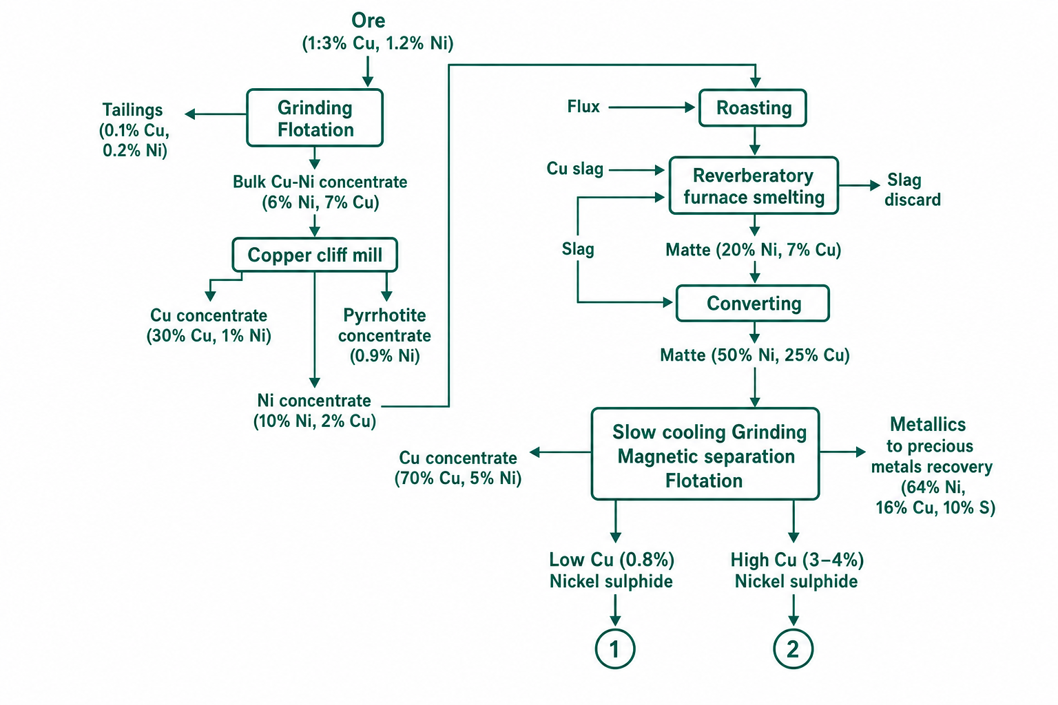
- Grinding + differential froth flotation → Cu concentrate, Ni concentrate, pyrrhotite concentrate.
- Roasting (fluidised bed, 550–600 °C) → 40% S oxidised; autogeneous; high SO₂ output.
- Reverberatory smelting + siliceous flux → matte (20% Cu, 7% Ni) + slag.
- Pierce-Smith converting (1150 °C) → Ni-enriched matte (50% Ni, 25% Cu, 21.5% S).
- Slow cooling (melt → 400 °C over 3 days) → Three phases: Cu₂S (top), Cu-Ni alloy (700 °C), Ni₃S₂ (575 °C).
- Magnetic separation + flotation → Cu₂S and Ni sulphide streams separately.
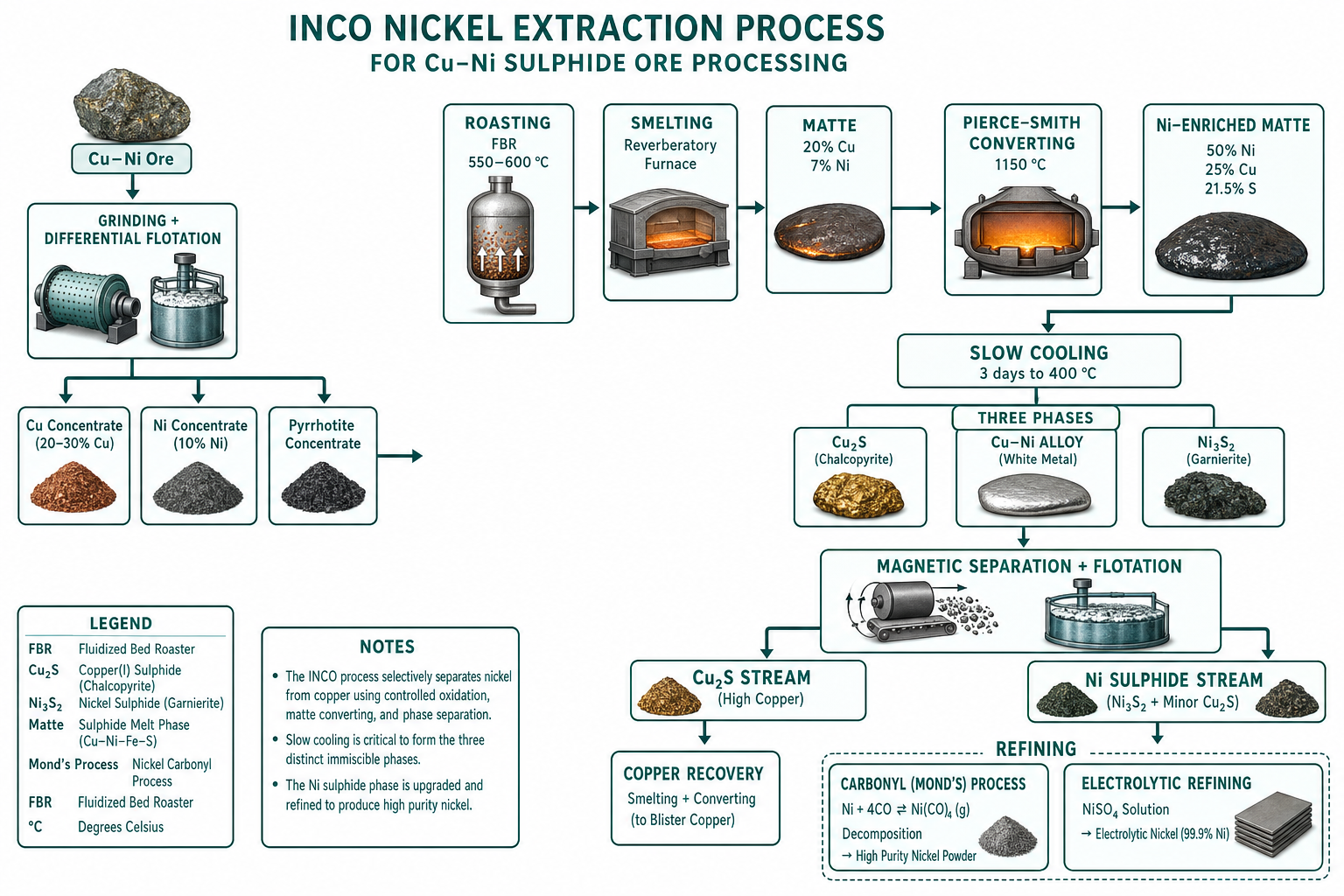
Slow cooling after converting is essential to achieve sufficient grain growth of Cu₂S, Ni₃S₂, and Cu-Ni alloy phases for effective subsequent flotation and magnetic separation. Three days of controlled cooling from the melt to 400 °C.
3 Carbonyl Refining — Mond's Process
At 40–90 °C, metallic Ni combines with CO to form gaseous nickel carbonyl [Ni(CO)₄]. At 150–300 °C, Ni(CO)₄ decomposes to give pure Ni metal and CO (recycled).
Ni + 4CO → Ni(CO)₄ | Ni(CO)₄ → Ni + 4CO
Fe(CO)₅ and Co₂(CO)₈ are also volatile but separated by fractional condensation. Cu does not form a volatile carbonyl. INCO Pressure Carbonylation: at 180 °C and 70 atm, carbonyls of Ni, Fe, and Co form; Ni(CO)₄ recovered by fractional distillation → Ni pellets or powder. Final purity: 99.97% Ni.
4 Electrolytic Refining
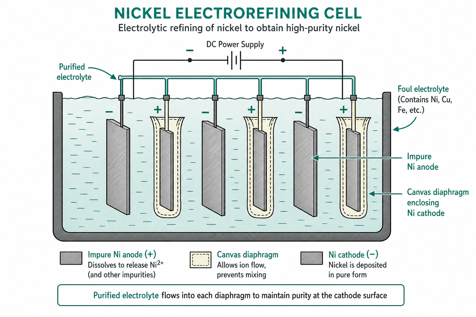
Ni oxide reduced by coke in electric furnace → cast as anode. Electrolyte: 60 g/L Ni²⁺, 95 g/L SO₄²⁻, 35 g/L Na⁺, 55 g/L Cl⁻, 16 g/L H₃BO₃ at 60 °C.
Uses of Ni: Ni-Cu alloys (Monel) for chemical/oil industry; German silver (Ni-Cu-Zn); stainless steel; nuclear reactors; Ni-based superalloys for jet engines.
Key Takeaways — Lecture 8
- INCO process: flotation → smelting → converting → slow cooling → magnetic separation + flotation → separate Cu₂S and Ni sulphide streams.
- Slow cooling essential for phase separation (Cu₂S, Ni₃S₂, Cu-Ni alloy) and flotation recovery.
- Mond's carbonyl: Ni(CO)₄ forms at 40–90 °C, decomposes at 150–300 °C → highly pure Ni without anode preparation.
- Electrolytic refining: 99.93–99.95% Ni; Cu removed by cementation; Co by oxidation.
Extraction of Magnesium
Three routes to magnesium metal — Dow process (sea water), electrolysis of MgCl₂, and Pidgeon / Magnotherm silicothermic processes.
Contents
1 Properties & Minerals of Magnesium
At. No. 12 | At. Wt. 24 | Density 1.738 g/cm³ | M.P. 650 °C | B.P. 1107 °C. The lightest structural metal.
Minerals: Dolomite (MgCO₃·CaCO₃); Magnesite (MgCO₃); Brucite [Mg(OH)₂]; Carnallite (MgCl₂·KCl·6H₂O); sea water (MgCl₂, MgSO₄). Indian: NML Jamshedpur; CECRI Karaikudi (Tamil Nadu).
2 Dow Process (Sea Water)
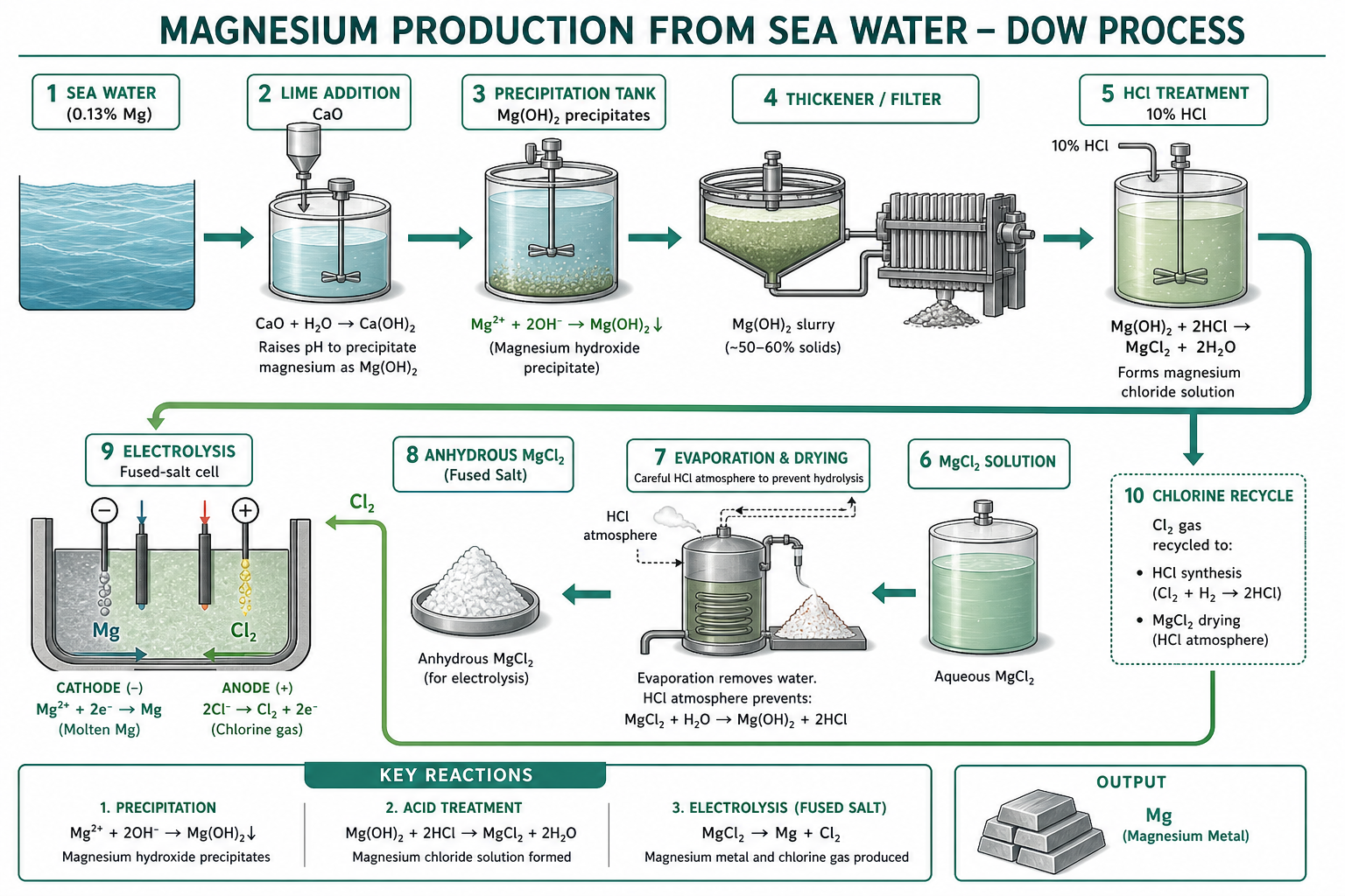
Sea water (~1.3 kg/m³ Mg as MgCl₂): Sea water + CaO → Mg(OH)₂ ↓ + Ca²⁺. Mg(OH)₂ filtered; dissolved in 10% HCl → MgCl₂. Concentrated and dried → anhydrous MgCl₂. Electrolysed → Mg (cathode) + Cl₂ (anode).
3 Electrolysis of MgCl₂
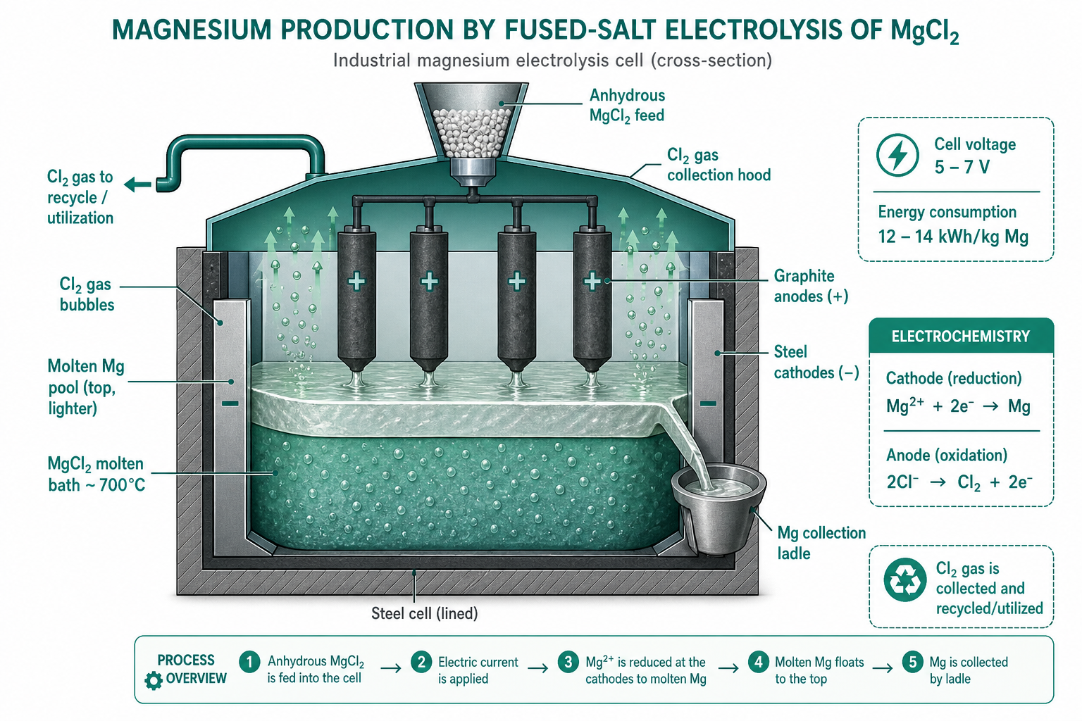
Aqueous electrolysis would evolve H₂ before Mg deposits — fused-salt electrolysis required. Bath: MgCl₂ + NaCl + KCl + CaCl₂ flux (reduces viscosity, increases conductivity). Cathode: steel; Anode: graphite. Mg (SG 1.74) floats on denser salt bath. Cl₂ collected in hood; recycled to dry incoming MgCl₂.
4 Pidgeon Process (Silicothermic)
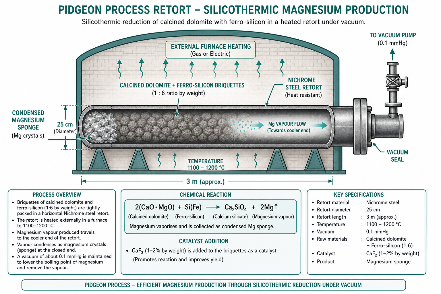
Calcined dolomite (CaO·MgO) + ferrosilicon (75% Si) in briquettes, heated at 1100–1200 °C under vacuum (0.1 mmHg) in a Nichrome-steel retort:
2(CaO·MgO) + Si(Fe) → Ca₂SiO₄ + 2Mg↑ (vapour)
Mg vapour condenses outside the retort. 120 t dolomite + 12 t ferro-Si → 10 t Mg (endothermic — external heat required). Small CaF₂ or MgF₂ addition acts as a catalyst.
5 Magnotherm Process & Uses
Similar to Pidgeon but operates at ~1500 °C with the bath in molten state, stabilised by Al₂O₃ addition to form molten slag. Higher throughput but more energy-intensive.
Uses of Mg: Structural — automotive (lightest structural metal, ⅓ weight of Al); non-structural — alloying element in Al alloys; desulphurisation and deoxidation of molten metal; Kroll process reductant for Ti; incendiary flares; die-casting alloys.
Key Takeaways — Lecture 9
- Dow process: sea water → Mg(OH)₂ → MgCl₂ → fused-salt electrolysis. Cl₂ by-product recycled.
- Fused-salt electrolysis essential — aqueous electrolysis evolves H₂ before Mg deposits.
- Pidgeon process: silicothermic; ferrosilicon reduces calcined dolomite at vacuum; batch; dominant in China.
- Magnotherm: same principle as Pidgeon but molten bath; higher throughput.
- Mg is the reductant in Kroll process (Ti), reinforcing its strategic importance.
Extraction of Aluminium
Bayer's process for alumina from bauxite, the Hall-Héroult electrolytic smelting cell, the anode effect, Hoopes electro-refining, and alternative ALCOA/Toth processes.
Contents
1 Properties & Minerals of Aluminium
At. No. 13 | At. Wt. 27 | Density 2.702 g/cm³ | M.P. 660.4 °C | B.P. 2467 °C.
Minerals: Bauxite (mixture of gibbsite Al₂O₃·3H₂O and diaspore Al₂O₃·H₂O) — chief ore; contaminated with Fe₂O₃, TiO₂, SiO₂. India: HINDALCO, NALCO, ALIND, MALCO. East Coast bauxite — among world's largest deposits.
Why not carbothermic reduction? Requires very high temperatures; forms Al₄C₃; needs expensive refractories. Why not aqueous electrolysis? H₂ evolves before Al deposits (insufficient H₂ overvoltage to bridge the 1.67 V gap). → Fused-salt electrolysis of Al₂O₃ is the only viable commercial route.
2 Bayer's Process — Alumina Production
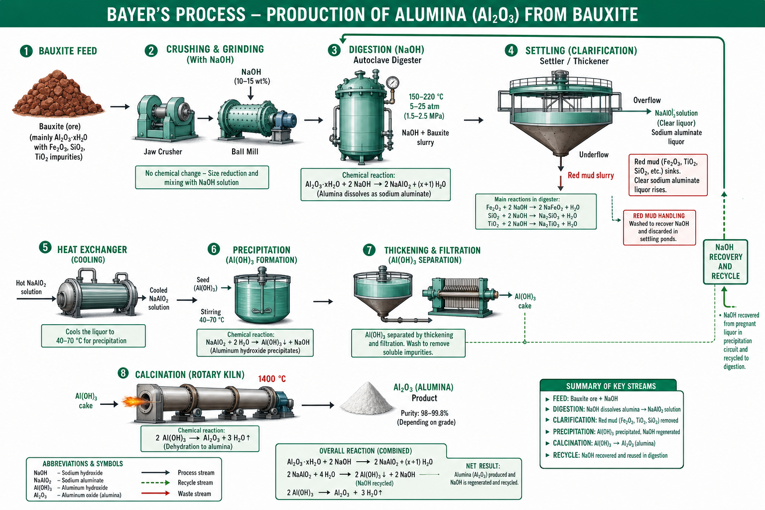
Bauxite crushed and ground with NaOH in ball mills → digestion at 150–220 °C and 5–25 atm:
Al₂O₃·3H₂O + 2NaOH → 2NaAlO₂ + 4H₂O (gibbsite) | Al₂O₃·H₂O + 2NaOH → 2NaAlO₂ + 2H₂O (diaspore)
Fe₂O₃, TiO₂, SiO₂ remain insoluble → red mud settled/filtered. Clarified liquor cooled → Al(OH)₃ precipitated by seeding. Calcined in rotary kiln at 1400 °C → anhydrous Al₂O₃.
3 Hall-Héroult Process
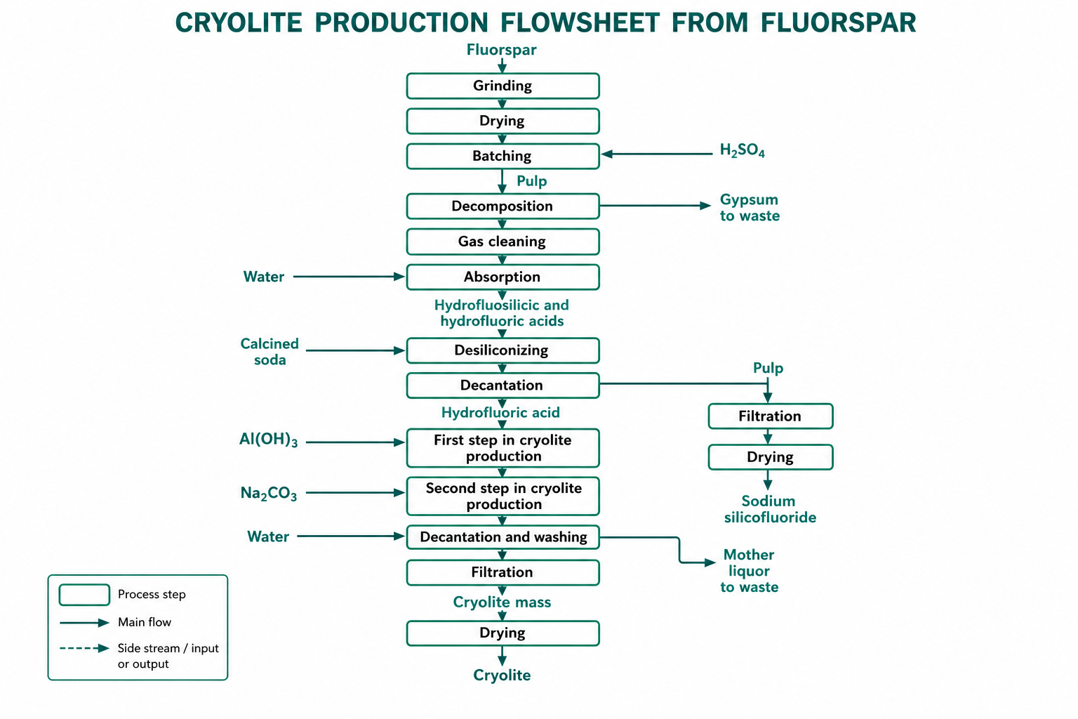
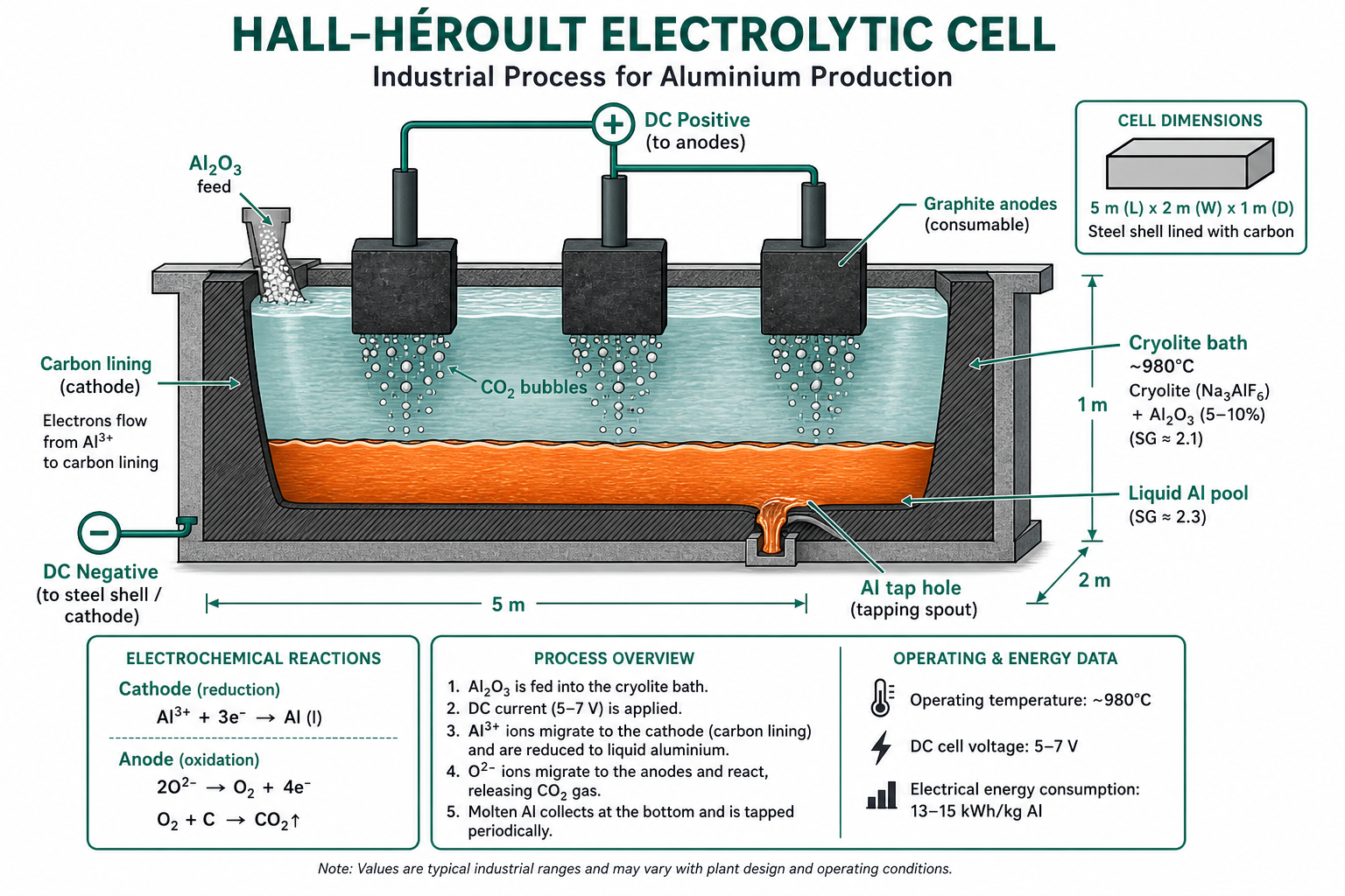
Al₂O₃ dissolved in molten cryolite (Na₃AlF₆) at ~980 °C (up to 15% Al₂O₃ dissolves). Additives: CaF₂ + NaF improve conductivity. Cell: rectangular steel box (5 m × 2 m × 1 m), C lining as cathode, consumable graphite anodes. 5–7 V DC, 100–300 kA. Energy: 13–15 kWh/kg Al.
Cathode reaction: Al³⁺ + 3e⁻ → Al (liquid, SG 2.3 — sinks below cryolite bath SG 2.1). Anode reaction: 2O²⁻ → O₂ + 4e⁻; O₂ + C → CO₂ (graphite consumed at ~0.5 kg C/kg Al).
4 Anode Effect
When Al₂O₃ content drops below 2%, the anode-bath contact is disrupted by a gas film → cell voltage spikes (10–40 V), current drops, normal operation ceases — called the anode effect. Corrected by vigorous agitation and immediate Al₂O₃ addition.
Causes: Thermal (local overheating → gas film) or electrostatic (charged gas bubbles form adherent film). Factors: Higher temperature, greater electrolyte purity, and graphite anodes reduce critical current density.
5 Hoopes Electro-refining & Alternative Processes
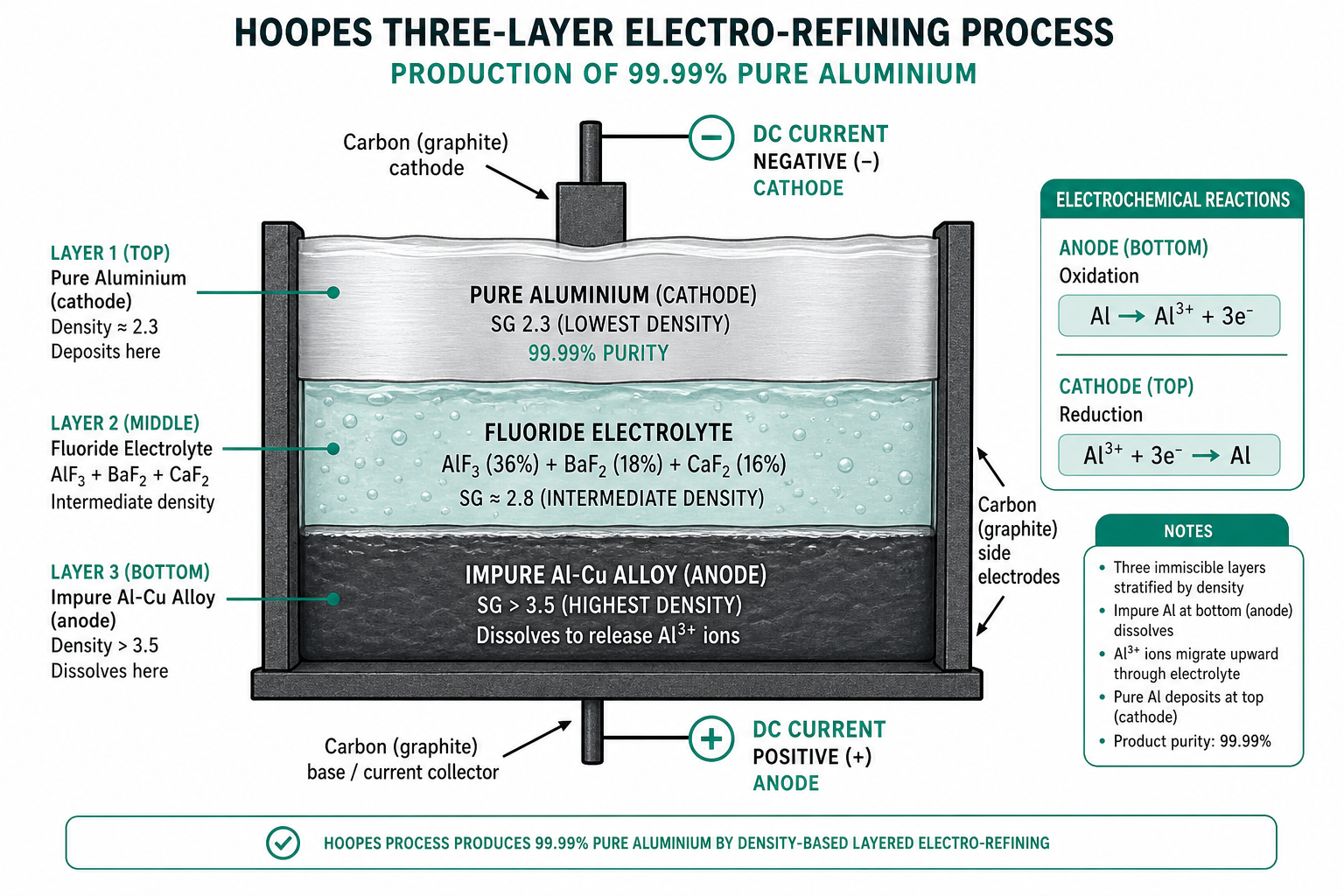
Hoopes three-layer process refines Al to 99.99% based on density stratification:
- Bottom (anode): impure Al-Cu alloy (SG > middle) — anode dissolves.
- Middle (electrolyte): AlF₃ (36%) + BaF₂ (18%) + CaF₂ (16%) — intermediate SG.
- Top (cathode): pure Al (SG 2.3) — deposits as cathode product.
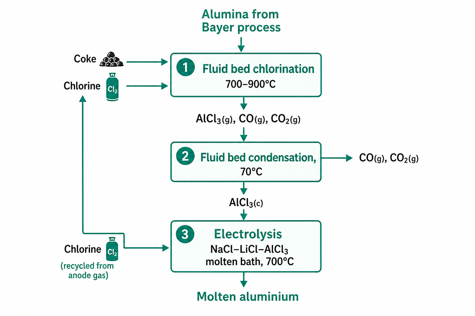
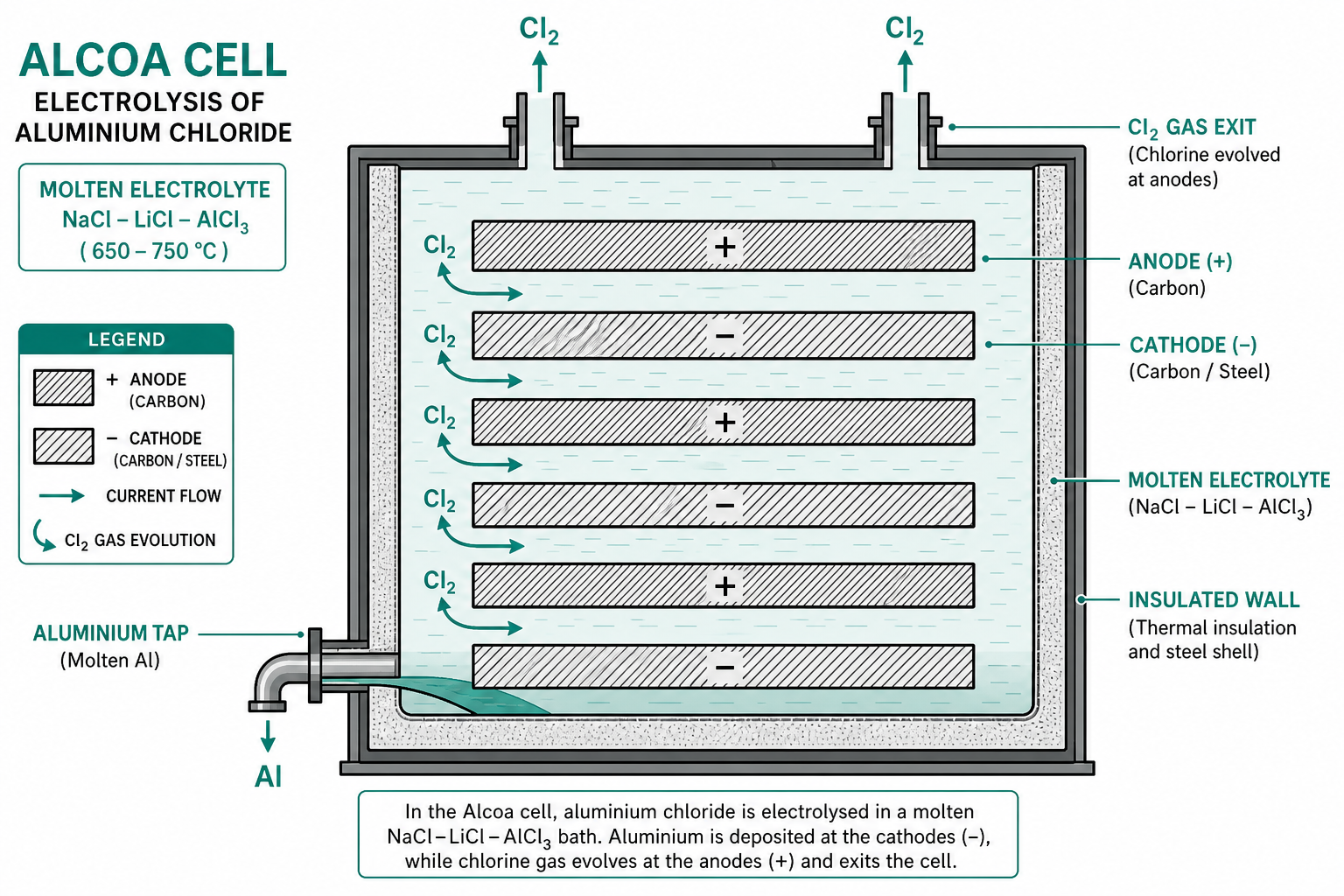
ALCOA Process: Al₂O₃ + 2Cl₂ + 3C → 2AlCl₃ + 3CO (chlorination at 700–900 °C) → AlCl₃ electrolysed in fused AlCl₃-NaCl-LiCl at 700 °C → Al (cathode) + Cl₂ (anode, recycled).
Uses of Al: Electrical conductors; aerospace structures (Al-Cu, Al-Mg, Al-Zn alloys); automotive lightweighting; food packaging; construction.
Key Takeaways — Lecture 10
- Bayer's process: NaOH digestion of bauxite → NaAlO₂ → Al(OH)₃ precipitate → calcined → Al₂O₃. Red mud is main waste.
- Hall-Héroult: Al₂O₃ in cryolite at 980 °C; 5–7 V; 13–15 kWh/kg Al; graphite anodes consumed as CO₂.
- Anode effect: Al₂O₃ <2% → gas film disrupts contact → voltage spike; corrected by agitation + Al₂O₃.
- Hoopes refining: three-layer density stratification → 99.99% Al.
- ALCOA process: AlCl₃ route; bipolar cells; lower energy but complex chlorine handling.
Extraction of Ti, Zr, Sn & Nb
Kroll's and Hunter processes for titanium; Kroll's process for zirconium; carbothermic reduction and refining of tin; and Nb/Ta extraction by aluminothermy.
Contents
1 Titanium — Kroll's Process
At. No. 22 | Density 4.54 g/cm³ | M.P. 1668 °C. Minerals: Rutile (TiO₂), Ilmenite (FeO·TiO₂). TiO₂ cannot be reduced by carbon (forms TiC). The Kroll process:
Step 1: TiO₂ + 2Cl₂ + 2C → TiCl₄ + 2CO (chlorination, 800–1000 °C)
Step 2: TiCl₄ + 2Mg → Ti (sponge) + 2MgCl₂ (800 °C, Ar atmosphere)
Ti sponge recovered by: (a) leaching MgCl₂ + excess Mg with dilute HCl, or (b) vacuum distillation of MgCl₂ and Mg. Max yield 96%. MgCl₂ electrolysed to regenerate Mg + Cl₂ (closed loop).
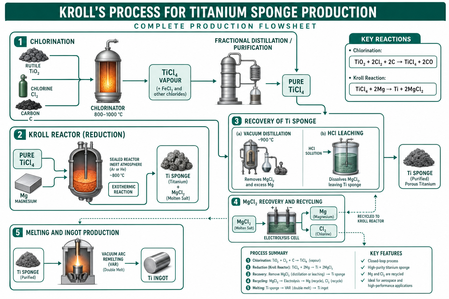
MgCl₂ by-product is electrolysed to regenerate Mg and Cl₂, closing the process loop. Ti sponge is consolidated by consumable-electrode vacuum arc melting (double VAR) for compositional homogeneity. No graphite crucibles — prohibitive C pick-up.
2 Titanium — Hunter Process
TiCl₄ reduced by sodium instead of Mg: TiCl₄ + 4Na → Ti + 4NaCl (highly exothermic). Reduction proceeds through sub-chlorides (TiCl₄ → TiCl₃ → TiCl₂ → Ti). The reaction in fused NaCl is electrochemical — Na oxidation at anodic sites, Ti sub-chloride reduction at cathodic sites.
Hunter process produces denser Ti with lower O, N, C contamination in some configurations. Uses: Jet engine compressor blades; airframes; missiles; spacecraft; medical implants. Indian extraction: Tuticorin (Tamil Nadu), Kerala (beach sand ilmenite).
3 Extraction of Zirconium
At. No. 40 | Density 6.45 g/cm³ | M.P. 1852 °C. Mineral: Zircon (ZrSiO₄). Key challenge: Zr/Hf separation (chemically nearly identical). Separation methods: differential oxidation of tetrachlorides; lower chloride formation; differential reaction of double chlorides with alkali chlorides. Then Kroll reduction of ZrCl₄ by Mg. Consolidated by double vacuum arc remelting.

Uses: Nuclear reactor cladding (low neutron capture cross-section); non-nuclear flash bulbs; ZrO₂ ceramics. Indian sites: Tarapur (Maharashtra), Kota (Rajasthan), Kalpakkam (Tamil Nadu).
4 Extraction of Tin
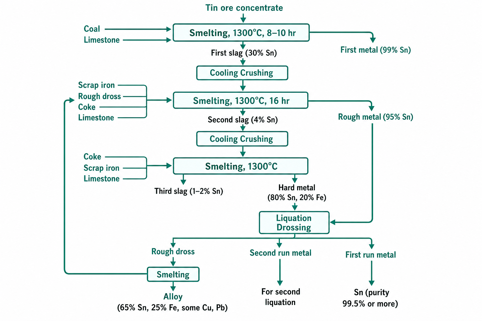
At. No. 50 | Density 7.31 g/cm³ | M.P. 231.9 °C. Mineral: Cassiterite (SnO₂). Carbothermic reduction feasible at moderate temperature. However, FeO is more stable than SnO₂ above 1200 °C — selective Sn reduction from Sn-Fe concentrate is difficult. Three-stage smelting:
- First stage: 99% Sn recovered; almost all Fe in slag (reverberatory or rotary furnace).
- Second and third stage: Slag reduced further; products purified by liquation.
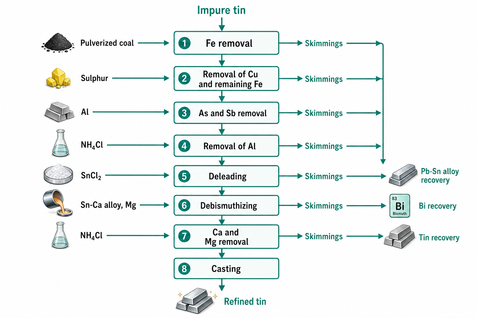
Pyrometallurgical refining: Impure Sn cooled just above 232 °C; intermetallics (Cu₂Sb, FeSn₂) of higher M.P. float and are skimmed. S removes Cu as CuS; Al removes As, Sb; NH₄Cl removes excess Al.
5 Extraction of Niobium
At. No. 41 | Density 8.57 g/cm³ | M.P. 2750 K. Minerals: Columbite [(Fe,Mn)(Nb,Ta)₂O₆]; Pyrochlore. Extracted jointly with Ta — separated by liquid-liquid extraction (MIBK or tributyl phosphate). Nb₂O₅ reduced aluminothermically or by C/H₂; consolidated by electron-beam or vacuum arc melting.
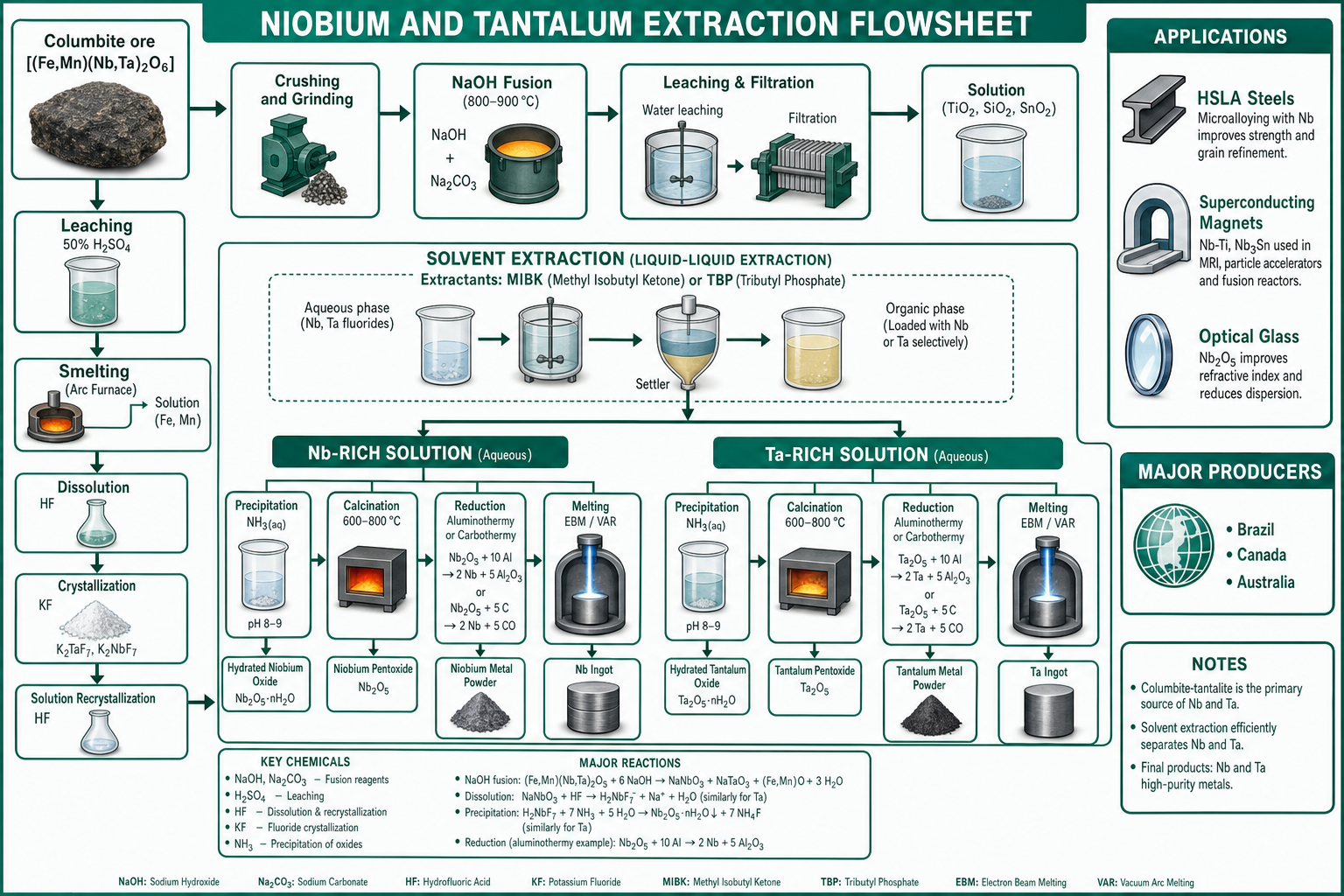
Uses of Nb: HSLA steel microalloying (0.04% Nb raises yield strength by ~100 MPa); jet engine alloys; superconducting magnets (Nb-Ti, Nb₃Sn) for MRI and particle accelerators; Nb₂O₅ in high-refractive-index optical glasses.
Key Takeaways — Lecture 11
- Ti: Kroll (TiCl₄ + Mg → Ti sponge + MgCl₂; Ar atmosphere) — ~80% world production; Hunter (Na reduction) gives denser Ti.
- Zr: Kroll process; key challenge is Zr/Hf separation; nuclear reactor cladding application.
- Sn: three-stage carbothermic smelting + liquation + pyrometallurgical/electrolytic refining → 99.95%.
- Nb: aluminothermic/carbothermic reduction; critical for HSLA steels and superconducting magnets.
Uranium Extraction & Environmental Control
Uranium leaching, purification, and conversion to nuclear fuel; and prevention and control of environmental pollution from non-ferrous extraction processes.
Contents
1 Properties & Minerals of Uranium
At. No. 92 | At. Wt. 238.03 | Density 19.1 g/cm³ | M.P. 1405 K | B.P. 4404 K. Uranium is the densest naturally occurring element. Mineral: Uraninite (UO₂). Major producers: Kazakhstan, Canada, Australia.
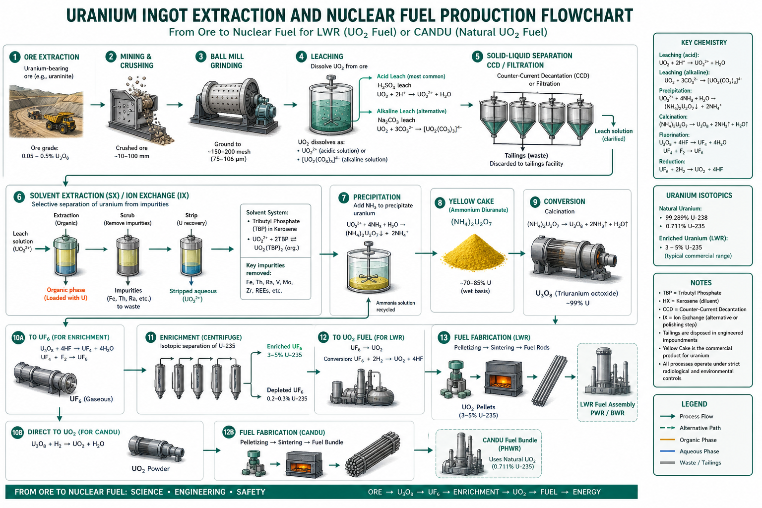
2 Extraction of Uranium
- Mining and crushing → ore ground to expose uraninite grains.
- Leaching: Acidic leach (H₂SO₄) or alkaline leach (Na₂CO₃) dissolves U as UO₂²⁺ or [UO₂(CO₃)₃]⁴⁻.
- Solid-liquid separation: Counter-current decantation (CCD) or filtration removes gangue (tailings).
- Purification: Solvent extraction (tributyl phosphate/kerosene) or ion-exchange resins selectively extract U from Fe, Th, Ra impurities.
- Precipitation: U stripped from solvent → ammonium diuranate ("yellow cake" — (NH₄)₂U₂O₇) by adding NH₃.
- Conversion: Yellow cake → UF₆ (for isotope enrichment of ²³⁵U) or UO₂ pellets (for natural-U CANDU reactors).
- Enrichment: Gaseous diffusion or centrifuge increases ²³⁵U from 0.7% to 3–5% for LWR fuel.
Natural uranium: 99.3% ²³⁸U + 0.7% ²³⁵U. Only ²³⁵U is fissile (sustains chain reaction). ²³⁸U absorbs neutrons to form ²³⁹Pu (fissile) in breeder reactors — extending the nuclear fuel supply.
3 Uses of Uranium
- Nuclear fuel: Enriched U (3–5% ²³⁵U) as UO₂ pellets in light-water reactors; natural U in CANDU heavy-water reactors.
- Naval propulsion: Highly enriched U (>90% ²³⁵U) powers nuclear submarines and aircraft carriers.
- Depleted uranium (DU): Very dense (19.1 g/cm³); ballast for ships; armour-piercing ammunition; radiation shielding.
- Breeder reactors: ²³⁸U → ²³⁹Pu — multiplies nuclear fuel supply.
4 Environmental Pollution from Extraction
- Particulate emissions: Dust from crushing, grinding, transfer points, casting operations.
- Gaseous emissions: SO₂ (major — from sulphide roasting and converting); CO, CO₂; As₂O₃ vapour; HF (from Al smelting cells).
- Noise pollution: Crushers, ball mills, fans.
- Waste water: Acid plant effluent, electrolyte spillage, cooling water containing heavy metals.
- Solid waste: Tailings, slag, red mud (Al), spent refractories, anode stubs.
- Fugitive emissions: From conveyor belts, stockpiles, open vessels, ladle transfers.
5 Prevention and Control Methods
- SO₂ capture: Rich SO₂ from flash smelting and fluid-bed roasters → double-contact double-absorption H₂SO₄ plant — >99.7% SO₂ capture.
- Primary gas treatment: Venturi scrubbers or waste-heat boilers cool furnace off-gas; cyclones as spark separators before bag filters.
- Secondary fume capture: Canopy hoods and evacuation systems over converters, ladles, and casting bays → bag house filters or electrostatic precipitators (ESP).
- Wet scrubbers: Capture water-soluble gases (SO₂, HCl, HF) — need additional effluent treatment facilities.
- Bag house filters / ESP: High particulate efficiency for sub-micron particles; in Al smelters, HF and Al₂O₃ fume captured by dry Al₂O₃ scrubbing (fume returned to pots).
- Stockpile management: Indoor/covered stockpiles; water spray systems; dust suppressants; enclosed conveyors; sealed silos for bulk powder.
- Effluent treatment: Neutralisation, precipitation, and clarification of acid mine water before discharge.
Best available technique (BAT): Flash smelting + contact H₂SO₄ plant + dry Al₂O₃ scrubbing for HF + ESP for fine dust achieves >99% capture of all major pollutants — the environmental benchmark for modern Cu and Al smelters.
Key Takeaways — Lecture 12
- Uranium: hydromet route — leaching → solvent extraction → yellow cake → UF₆/UO₂ → enrichment.
- ²³⁵U (0.7% natural) is the only naturally fissile nuclide; ²³⁸U → ²³⁹Pu in breeder reactors.
- Major pollutants: SO₂ (smelting), particulates (comminution), HF (Al cells), acid water, slag.
- Control: rich SO₂ → contact H₂SO₄; bag filters/ESP for particulates; dry scrubbing (Al); enclosed conveyors for fugitives.
- Flash smelting + contact acid plant is the global environmental benchmark for Cu smelting.
References
- Ray, H.S., Sridhar, R., & Abraham, K.P. (2014). Extraction of Nonferrous Metals. Affiliated East-West Press.
- Biswas, A.K. & Davenport, W.G. (1994). Extractive Metallurgy of Copper (3rd ed.). Pergamon Press.
- Habashi, F. (1997). Handbook of Extractive Metallurgy. Wiley-VCH.
- Mishra, D.K., Behera, G., & Lava Kumar, A. (2023). Lecture Notes on Non-Ferrous Extractive Metallurgy. VSSUT Burla.